What is Rogers PCB?
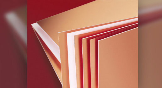
Rogers Corporation is a company that manufactures circuit board materials. Rogers laminates are generally used in high-speed, commercial microwave, and radio frequency applications. They offer superior dielectric constant and temperature stability when compared with standard FR4 materials. Its minimal water absorption characteristic makes it appropriate for use in high-humidity applications.
Why Rogers PCB material?
Although Rogers laminates are a bit more expensive than other materials, they perform well in challenging conditions. Here are the reasons to go for Rogers materials:
- Reduced electrical signal and dielectric losses
- Low outgassing when used in space applications
- Improved controlled impedance
- Most suitable in high power applications
- Enhanced plated through hole (PTH) reliability
- Improves heat sink performances
- Better dimensional stability
- Low CTE values make it ideal for space and radar applications
- Offers a wide range of dielectric constants (2.55 to 10)
High-Speed Material Design Guide
6 Chapters - 19 Pages - 30 Minute ReadWhat's Inside:
- Importance of choosing the right material for your high-speed design
- Parameters that affect material selection
- Effect of dielectric constituents on your circuit board
- Characteristics of high-speed materials
- Effect of resin content and glass weave structure on your PCB
Download Now
Features of Rogers laminates
The below table lists some of the important features of Rogers board materials.
| Thermal conductivity (k) | 1.6 W/m-K in the Z-axis |
| Glass transition temperature (Tg) | Greater than 280°C |
| Decomposition temperature (Td) | Up to 350°C |
| Coefficient of thermal expansion (CTE) | 20 ppm/°C |
| Loss tangent | 0.0014-0.003 at 10 GHz |
| Dielectric constant (Dk) | 2.5-10 |
What is the difference between Rogers and FR4 materials?
The overall performance of a circuit board mainly relies on the materials chosen to fabricate it. Rogers and FR4 materials are among the most popular board materials. Hence, it is essential for PCB designers to know the difference between these two.
FR-4 is typically epoxy combined with woven glass. Generally, Rogers materials are made of ceramic combined with woven glass.
Cost
FR-4 materials are less expensive compared to Rogers. If there is a budget constraint, then FR-4 materials will be a better choice. To fabricate a highly reliable circuit board it is recommended to opt for Rogers material. When it comes to other high-speed materials a special manufacturing process might be required. But in the case of Rogers, it can be processed similarly to FR-4.
Controlled impedance
Impedance is the measurement of the restriction imposed by a circuit on the current flow. PCB signal traces must have a uniform regulated impedance to prevent signal distortions induced by signal reflections. Rogers materials offer uniform controlled impedance with minimum tolerance in contrast to standard FR-4 materials.
Thermal management
High-power components such as MOSFETs, high-performance processors, high-power LEDs, and IGBTs are used in modern electronics. These components operate under extreme temperatures. Rogers materials offer better thermal properties. They are more suitable for applications with high operating temperatures. Read, 12 PCB thermal management techniques to reduce heating.
Applications of Rogers PCBs
Below are a few applications of Rogers laminates
Antenna systems

Rogers offers a diverse range of antenna-grade circuit laminates to fulfill the stringent requirements of military antenna systems and modern automobile radar systems. These materials are engineered for excellent reliability and consistent performance with minimal circuit losses at high frequencies.
Avionics
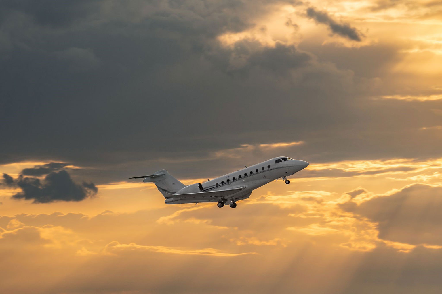
Circuit boards that are used in the avionics sector should be able to tolerate extreme temperature swings, shock, vibrations, and pressure changes. The excellent thermal properties of Rogers make them ideal for avionics equipment.
Communication systems

Rogers laminates not only offer reduced loss for advanced RF and microwave applications but also have a very well-controlled dielectric constant. Controlling the material’s dielectric constant can be just as important as controlling the substrate thickness in many RF subsystem applications.
Rogers PCB manufacturing considerations
Surface preparation
- A chemical process consisting of cleaning, micro-etching, water rinsing, and drying is the preferred method of surface preparation, especially for thinner core materials.
- Mechanical scrubbing should only be considered for the cores that are thicker than 60 mils. Scrubbing should also be performed with reduced pressure to avoid imparting scratches on the laminates since scratches lessen the spacing between traces.
Multi-layer bonding
- Rogers cores can be prepared for multi-layer bonding using any oxide or oxide alternative process that is also used for high Tg FR4 material systems.
- Inner-layer cores should be baked in a rack for 30 minutes at 107°C to 121°C (225F to 250F) prior to layup.
Drilling
- Drilling vias/holes using CO2, UV or CO2/UV combination lasers are preferred when aspect ratios permit.
- A post-laser clean with alkaline permanganate or CF4/O2 plasma can be used to ensure a good electrical connection to copper pads at the base of vias.
- Standard aluminum or pressed phenolic entry and exit materials are acceptable for mechanical drilling.
Copper plating and outer-layer processing
- Panel and pattern processing using electrolytic tin plating and acid copper is compatible with Rogers.
- The materials can then be treated using any standard strip/etch/strip (SES) method after plating.
- After etching, surfaces should bond very well to direct screened and photo-imageable solder masks.
- A short bake for 30-60 minutes at 110°C to 125°C may be required to ensure the board surfaces are dry prior to applying the solder mask.
Material information of R4350B
This PCB material is generally preferred for very high-speed applications.
| Material | Rogers RO4350B |
|---|---|
| Description | Hydrocarbon-Ceramic / Woven E-Glass |
| Application area | Very High Speed / Frequency, Very Low Loss |
| Offered at Sierra Circuits | Yes |
| HDI preferred | Yes |
| IPC designation | IPC-4103 |
| Slash designation | /11 |
| RoHS | Yes |
| CAF resistant | Yes |
| CTI class | 0 |
| CTI voltage | Greater than 600 |
| Glass transition temperature (Tg) | 280°C |
| Decomposition temperature | 390°C |
| Dielectric constant at 100 MHz | 3.48 |
| Dielectric constant at 1 GHz | 3.48 |
| Dielectric constant at 10 GHz | 3.48 |
| Dissipation factor at 100 MHz | 0.002 |
| Dissipation factor at 1 GHz | 0.002 |
| Dissipation factor at 10 GHz | 0.002 |
| Electrical Strength: (volts/mil) | 780 |
| Moisture absorption (%) | 0.06 |
| CTE Z axis (ppm/°C) pre Tg | 32 |
| CTE z axis (ppm/°C) post Tg | 32 |
| CTE X/Y axis (ppm°C/) lower limit | 10 |
| CTE X/Y axis (ppm°C/) upper limit | 12 |
| Thermal conductivity (W/mK) | 0.69 |
| Dimensional stability MD (<) % | 0.50% |
To get a comparison of Rogers materials and their properties such as Tg, Td, and Dk, try our Material Selector Tool.
With the advancements in electronic devices, circuit board materials such as Rogers are a must to ensure minimum signal losses in high-frequency applications such as aerospace, defense, and communication systems.


