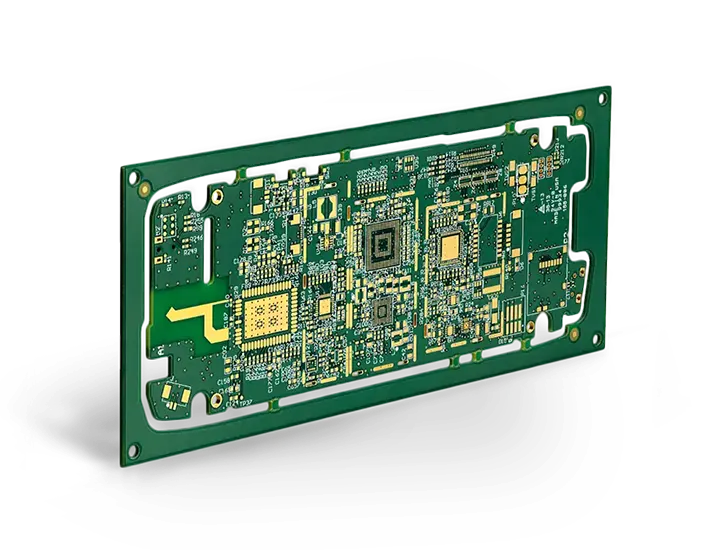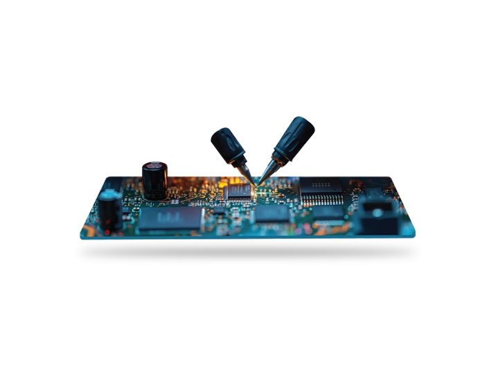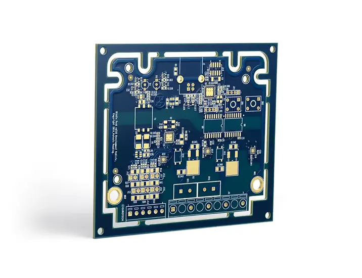
Controlled impedance helps you maintain data integrity and signal clarity.
Maintaining data and signal integrity is paramount in high-frequency PCBs, and controlled impedance plays a crucial role in achieving these objectives. Sierra Circuits stands as a reliable partner, offering comprehensive assistance whether you are in the early stages of design or troubleshooting an assembly problem.
Sierra Circuits can:
- Help you with your controlled impedance stack-up
- Route your single-ended and differential pair traces
- Place your components, vias, coupling capacitors
- Adjust the length matching to achieve propagation delay
- Calculate the effective dielectric constant
- Deliver -/+ 5% impedance tolerance

We are committed to helping you achieve your impedance requirements.
Our expertise extends across various aspects of controlled impedance, empowering you to navigate the complexities of high-frequency PCBs with confidence. From assisting you with a meticulously planned controlled impedance stack-up to ensuring optimal routing for both single-ended and differential pair traces, we are committed to enhancing the performance of your designs.
At Sierra Circuits, our support goes beyond the theoretical aspects. We provide guidance in strategic component placement, vias, and coupling capacitors to optimize signal integrity. Our team excels in adjusting length matching to achieve precise propagation delay, contributing to the overall reliability of your high-speed board.
Understanding the significance of effective dielectric constant, we employ advanced calculations to fine-tune the parameters that influence controlled impedance. With Sierra Circuits, you can rely on our commitment to delivering controlled impedance solutions with a tolerance of -/+ 5%. This precision ensures that your electronics meet the stringent requirements of signal integrity and operate seamlessly in diverse applications.
Whether you are embarking on a new design journey or troubleshooting existing challenges, Sierra Circuits provides the expertise and support needed to navigate the intricacies of controlled impedance, empowering you to achieve optimal performance in your high-frequency PCB projects.

Sierra Circuits supports IPC-2581.
In the PCB manufacturing landscape, IPC-2581 Revision C stands as a crucial standard for the seamless exchange of design data, particularly emphasizing controlled impedance for your high-speed PCBs. This open, vendor-neutral XML format plays a vital role in navigating the intricacies of PCBs, facilitating clear communication regarding layer stack-up, drill details, and other critical specifications. Using IPC-2581 helps designers and manufacturers ensure transparent data exchanges, effectively minimizing the likelihood of errors during the process.
Product Promise
Sierra Circuits understands the importance of controlled impedance and has developed a toolkit to help you optimize costs to preserve signal integrity.
Stackup Designer
Get precise options for cost-optimized stack-up structures! Our Stackup Designer has an integrated Impedance Calculator to get desired impedance and trace/space values on any signal layer.
Impedance Calculator
Calculate your trace widths, single-ended or differential impedances – for both microstrip and stripline models – and other parameters such as the dielectric height, the dielectric constant, and the trace thickness.
Materials Selector
Search and compare properties and specs for 60+ board materials to fit your application. Get specs for dielectric constant, dissipation factor, glass transition temperature, decomposition temperature, moisture absorption, and more.
Why Controlled Impedance is Important
Every day, PCB designs and components become smaller, faster – in other words, more complicated. It is now crucial to slow certain circuits down in order to allow specific functions of components to perform before others. The time of simple interconnecting traces and conductors is over.
Typically, you will need controlled impedance for PCBs used in high-speed digital applications, such as RF communication, telecommunications, computing using signal frequencies above 100 MHz, high-speed signal processing, high-quality analog video, etc.
At high-frequency signals, the signal traces on a PCB act like transmission lines, which have an impedance at each point on the signal trace trajectory. If this impedance varies from one point to the next one, there will be a signal reflection whose magnitude will depend on the difference between the two impedances. The larger the difference is, the greater the reflection will be. This reflection will travel in the opposite direction of the signal, which means that the reflected signal will superimpose on the main signal.
As a result, the original signal will be distorted: the signal intended to be sent from the transmitter side would have changed once it gets to the receiver side. The distortion may be so much that the signal may not be able to perform the desired function. Therefore, to have an undistorted signal travel, it is essential that the PCB signal traces have a uniform controlled impedance to minimize signal distortions caused by reflections. This is the first step to improve the integrity of the signals on the PCB traces.
Trusted by innovators
Engineers at the world’s most innovative companies choose Sierra Circuits to wrangle the impedance issues on their prototypes, right here in the USA.


Need help wrangling signal distortion away from your PCBs?
Bring your high-frequency circuits to life.
The time of simple interconnecting traces and conductors is over. With high-speed PCBs, it is crucial to slow certain circuits down to allow specific functions of components to perform before others.
Impedance control is required for high-speed PCBs used in:
- Digital applications, such as RF communication and telecommunications
- Computing, using signal frequencies above 100MHz
- High-speed signal processing
- High-quality analog video such as DDR, HDMI, Gigabit Ethernet
Sierra Circuits engineers know the importance of controlled impedance and will help you efficiently design and manufacture your boards with industry-leading impedance tolerances.


Manufacturing Equipment at Sierra Circuits
Our 70,000 sqft state-of-the-art campus in the heart of Silicon Valley contains the most advanced equipment required for the manufacture and assembly of your PCBs. Whether you’re looking for standard quick turn PCBs or boards with the tightest tolerances, made from exotic metals, there’s a reason Sierra Circuits leads the industry in quality and performance.
Get started with Controlled Impedance
Let us help you get control of your signal distortion with controlled impedance. Upload your data and receive a free consultation and review of your design today.
Start a Custom QuoteFabrication, Procurement, & Assembly. PCBs fully assembled in as fast as 5 days.
- Bundled together in an entirely-online process
- Reviewed and tested by Engineers
- DFA & DFM Checks on every order
- Shipped from Silicon Valley in as fast as 5 days
Fabrication. Procurement & Assembly optional. Flexible and transparent for advanced creators.
- Rigid PCBs, built to IPC-6012 Class 2 Specs
- 2 mil (0.002″) trace / space
- DFM Checks on every order
- 24-hour turn-times available
Complex technology, with a dedicated CAM Engineer. Stack-up assistance included.
- Complex PCB requirements
- Mil-Spec & Class 3 with HDI Features
- Blind & Buried Vias
- Flex & Rigid-Flex boards


