Speak to an Account Manager
![]() +1 (800) 763-7503
+1 (800) 763-7503
Tools for Designers:
RLC Resonant Frequency and Impedance Calculator
Try This New ToolSierra Circuits’ RLC Resonant Frequency and Impedance Calculator computes resonant frequency and impedance of series and parallel RLC circuits. The resonant frequency is the frequency at which a circuit’s highest oscillatory response occurs. This can be seen in circuits having capacitors and inductors. Generally, a resistor is introduced in resonant circuits to decay the oscillations. This process is known as damping. RLC (resistor, inductor, and capacitor) circuits are one of the most fundamental circuits used in PCB layouts. Hence, it is essential for a board designer to know about the resonant frequency and impedance of an RLC circuit.
The RLC Resonant and Impedance Calculator determines the capacitive reactance, inductive reactance, resonant frequency, impedance (parallel/series), and the quality factor without having to insert too many input parameters.
Features of the tool
- Calculates capacitive reactance, inductive reactance, resonant frequency, impedance (parallel/series), and quality factor
- Allows you to choose between series and parallel RLC combinations
- The units of the inputs and outputs can be changed using the respective dropdowns
- A brief description of each parameter can be viewed by clicking on the help button
How to use RLC Resonant Frequency and Impedance Calculator
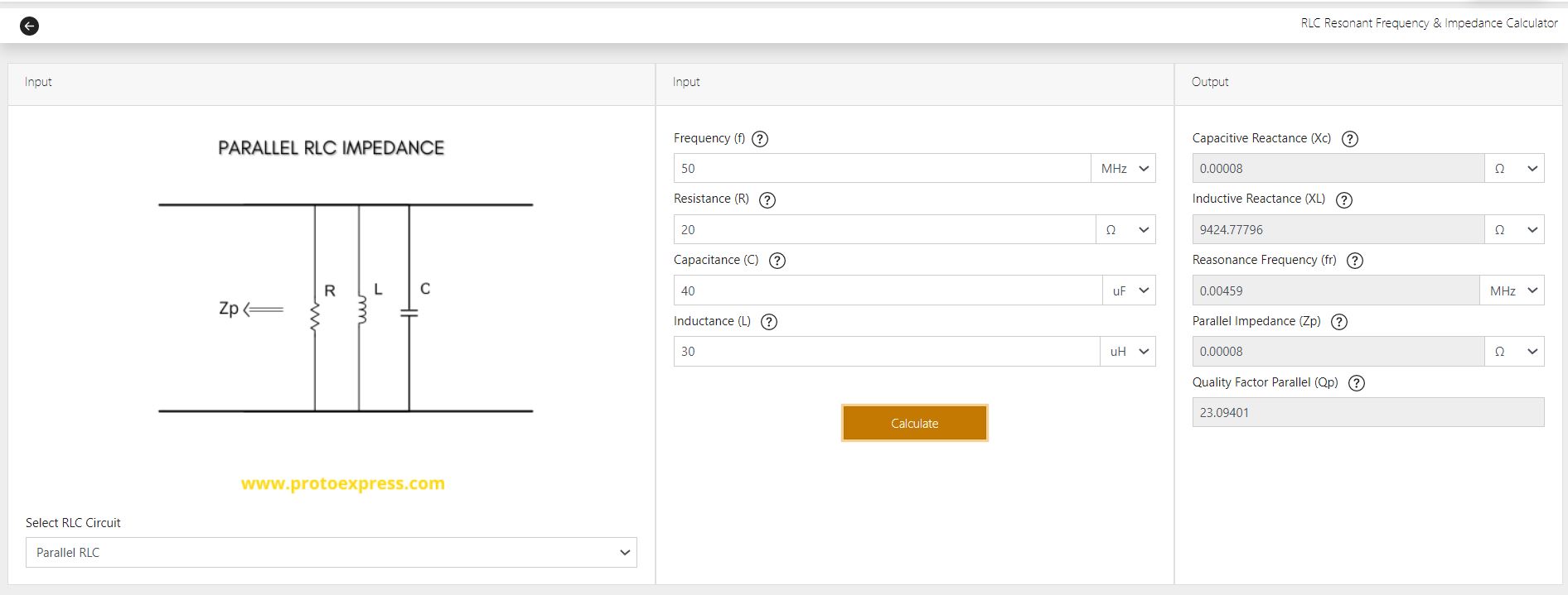
First, select the desired RLC connection (parallel/series). Next, input the following the parameters:
- Frequency (f)
- Resistance (R)
- Capacitance (C)
- Inductance (L)
The units of these parameters can be changed using the respective drop-downs.
Once you enter the values of all the required fields, hit calculate. The tool now displays the values of the following output parameters:
- Capacitive reactance (XC)
- Inductive reactance (XL)
- Resonance frequency (fr)
- Series impedance (ZS) or parallel impedance (ZP)
- Quality factor series (QS) or quality factor parallel (QP)
If you would like to learn more about any of these input/output parameters, click on the respective help button.
RLC circuits are widely incorporated in low-speed, high-speed, and RF applications such as filters, power delivery networks (PDN), and impedance matching networks. To analyze the behaviors of capacitors and inductors, it is important to calculate capacitive and inductive reactances. This can sometimes be a challenging and time-consuming task for designers who work on RF and high-speed applications. To expedite this process, you can use this RLC Resonant Frequency and Impedance Calculator.
Watch the tool demo:
Sierra Circuits has developed easy-to-use tools for PCB designers and electrical engineers at every stage of circuit board development.


Fabrication, Procurement, & Assembly. PCBs fully assembled in as fast as 5 days.
- Bundled together in an entirely-online process
- Reviewed and tested by Engineers
- DFA & DFM Checks on every order
- Shipped from Silicon Valley in as fast as 5 days

Fabrication. Procurement & Assembly optional. Flexible and transparent for advanced creators.
- Rigid PCBs, built to IPC-6012 Class 2 Specs
- 2 mil (0.002″) trace / space
- DFM Checks on every order
- 24-hour turn-times available

Complex technology, with a dedicated CAM Engineer. Stack-up assistance included.
- Complex PCB requirements
- Mil-Spec & Class 3 with HDI Features
- Blind & Buried Vias
- Flex & Rigid-Flex boards