When placing components on a PCB, their correct orientation and polarity matter. If wrongly placed, it will disrupt the functionality and cause component failures. Hence, it is vital to identify the positive and negative pins of a component before mounting it on a circuit board.
What does component polarity mean?
Component polarity helps to identify a part’s positive and negative terminals. In polarized components, the accurate placement of these terminals is essential for the component to function efficiently. Silkscreen markings in your layout generally indicate the components’ mounting direction.
What are positive and negative polarities in electrical components?
When current flows between two points or poles, one of the poles will have more electrons accumulated than the other.
The pole with fewer electrons is called the positive terminal. The pole having more electrons is called the negative terminal. Electrons flow from the negative pole towards the positive pole when a wire connects the two points or poles.
What does it mean when an electrical component is polarized?
A component may either be polarized or non-polarized. You can connect a non-polarized component in any direction. However, you must connect a polarized component in a specific direction to ensure it functions properly.
| Polarized components | Non-polarized components |
|---|---|
| Diode | Resistor |
| LED | Isolated resistor pack |
| Tantalum capacitor | Monolithic and ceramic capacitor |
| Electrolytic capacitor | Inductor |
| DIP and PLCC socket | Crystal oscillator/resonators (2-pin version) |
| Integrated circuit (IC) | |
| Transistor | |
| Crystal oscillator/resonators (multipin version) |
Before we talk about identifying component polarity, let’s quickly review the 5 best practices for labeling polarized parts in your layout.
5 best practices for marking polarized components in your layout
The below tips can reduce assembly errors, minimize production delays, and improve product quality.
- Follow IPC standards:
- IPC-7351B for component land patterns and IPC-2221 for general PCB design guidelines, including polarity markings
- Provide comprehensive documentation:
- Detailed schematic drawings.
- Assembly drawings with clear polarity markings for all polarized parts.
- Specification documents that identify polarity and orientation for all components.
- Use consistent and clear silkscreen markings:
- Standard symbols for polarized parts (e.g., diode symbols, capacitor polarity markings).
- Visible silkscreen markings not obscured by parts or other markings.
- Implement internal verification process:
- Develop a systematic approach to verify component polarity based on available documentation.
- Establish a protocol for addressing ambiguities or inconsistencies in design documentation.
- Communicate the exceptions:
- Convey any non-standard polarity markings or conventions used in the design.
- Provide additional information or clarification if the manufacturer requests.
For a cost-efficient PCB assembly, download our design guide.

PCB Design for Assembly Handbook
6 Chapters - 50 Pages - 70 Minute ReadWhat's Inside:
- Recommended layout for components
- Common PCB assembly defects
- Factors that impact the cost of the PCB assembly, including:
- Component packages
- Board assembly volumes
Download Now
How to identify the component orientation and polarity
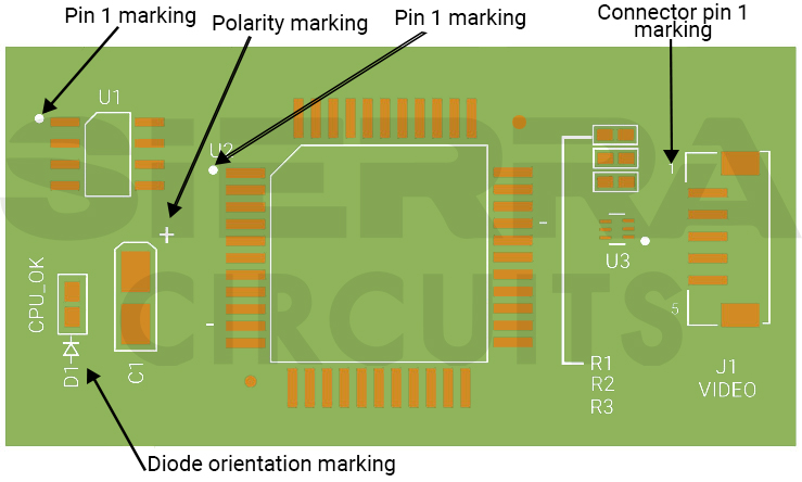
PCB assembly notes often include text annotations like “+” and “-” markings and symbols indicating the polarity. As a PCB designer, you can avoid incorrect connections and potential damage by adding polarities and pin 1 marking on the PCB silkscreen.
To learn how to specify pin 1 marking using a silkscreen layer, read how to add and identify pin 1 marking in your PCBs.
Resistors
Resistors are non-polarized. You can connect them in any direction. While placing resistors, match their values with the component list. Check for resistor color code and use a multimeter if needed.

Diodes
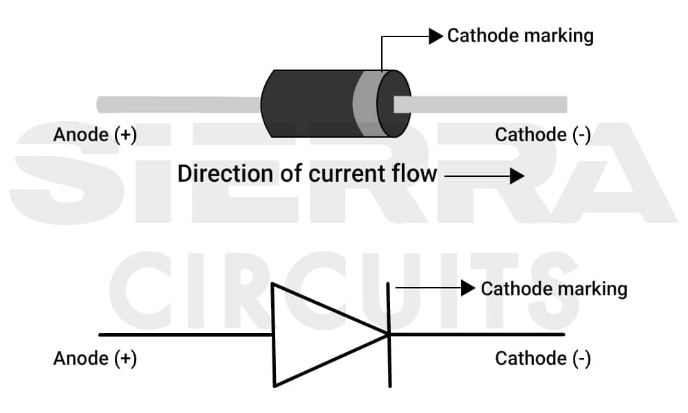
A diode is a two-terminal part that allows current to flow in only one direction, with the positive terminal being the anode and the negative terminal being the cathode. Current flows from the anode to the cathode.
Let’s see how to identify polarity markings on diodes:
- In a standard through-hole diode, the cathode is marked with a colored band at one end. For example, in the below diode, the cathode is on the right side, indicated by a band.
- SMD diodes similarly indicate cathode. The line indicating the cathode can be of various thicknesses, but it is always on the cathode side.
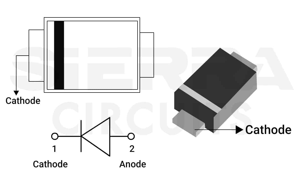
To learn about surface mount package sizes, see different SMD component package sizes.
LEDs
LEDs are diodes that allow current to flow in only one direction. These diodes light up when you connect them to a voltage source.
Here’s how you can determine the polarity of an LED:
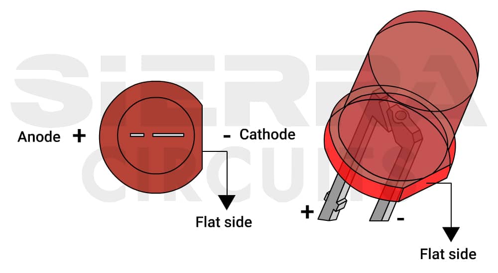
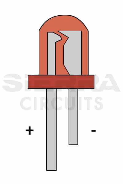
- An LED has leads of different lengths; the longer lead is positive (anode), and the shorter lead is negative (cathode).
 lead and a shorter negative lead (cathode).")
- The flat end of an LED indicates the negative lead. This makes it easy to identify the polarity without any tools.
- Inside an LED, there are two metal plates of different sizes. The larger plate is typically connected to the negative lead, while the smaller one is connected to the positive terminal. This method may not apply to all LED types.
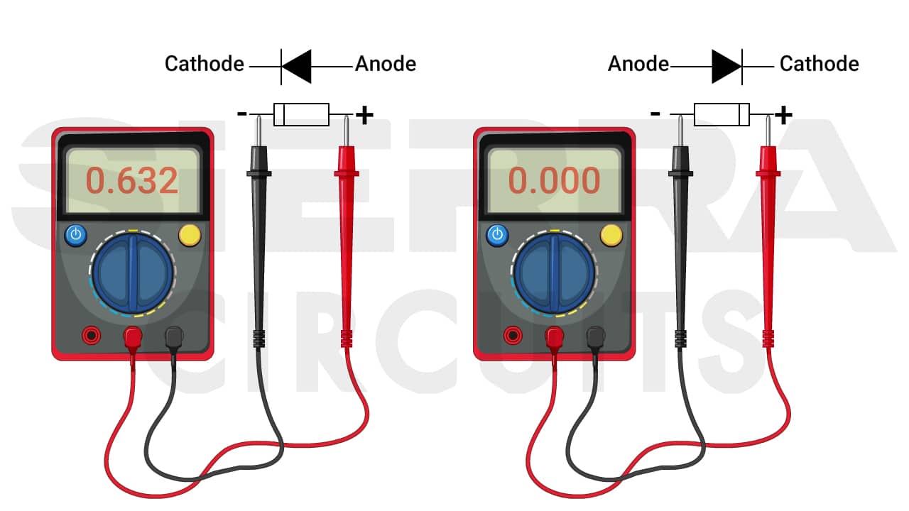
- A multimeter can measure the diode’s polarity. Turn the multimeter knob towards the diode symbol and connect the probes to the LED. The diode lights up if it is forward-biased (positive terminal of the multimeter connected to the anode; negative terminal connected to the cathode).
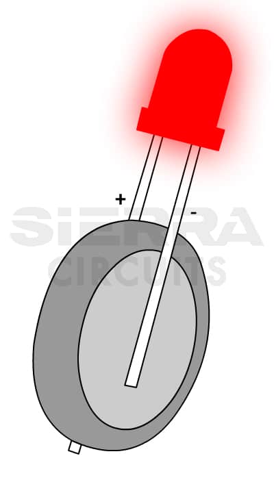
- A small coin cell battery can test the LED. If the LED lights up when connected to the battery, the anode is the lead touching the battery’s positive terminal.
Capacitors
Capacitors can be classified into two main types based on their polarity: polarized and non-polarized.
Polarized capacitors consist of an anode and a cathode. The cathode comprises a gel, liquid, or solid electrolyte surrounding the anode. The anode is a metal forming an anodized layer within a dielectric material.
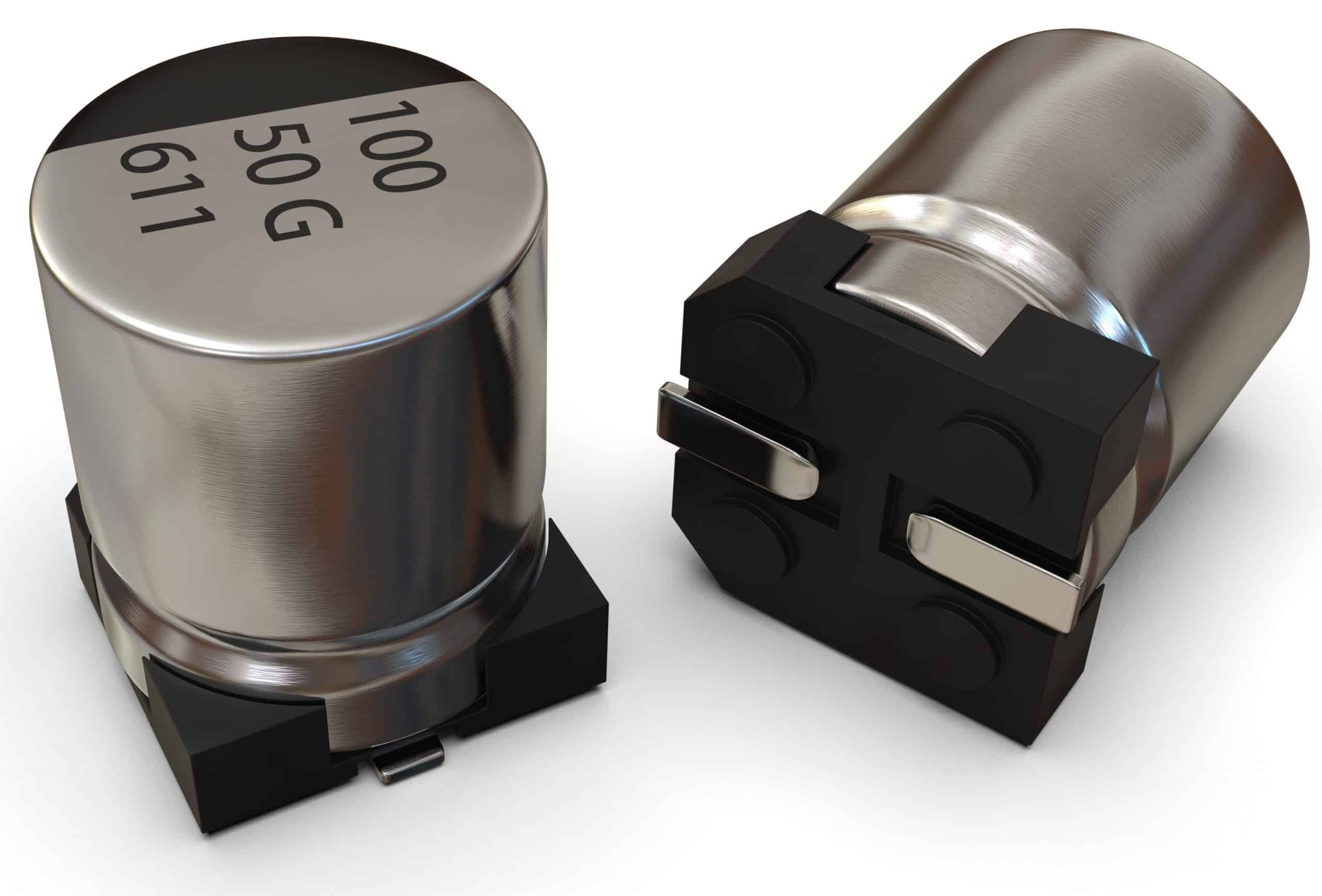
- Capacitors typically have straightforward polarity markings: a plus (+) sign for the positive terminal and a minus (-) sign for the negative terminal. In the below image, shorter lead and line arrows indicate negative terminal.
- Radial surface-mounted capacitors use color coding to indicate polarity; a small black section on top marks the negative terminal, while a gray section indicates the positive terminal.
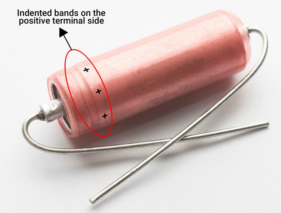
- Axial capacitors sometimes have an indented band on the positive terminal side.
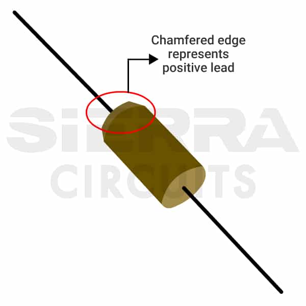
- Some solid tantalum axial capacitors have chamfered edges or dashes on the positive lead.
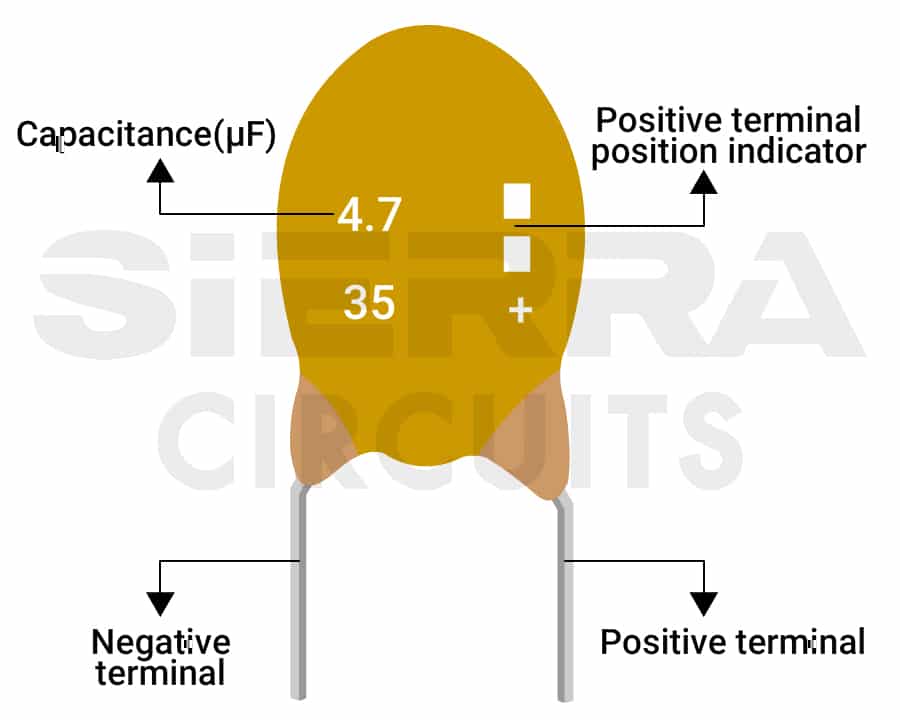
- Tantalum electrolytic capacitors may feature dashes, a plus sign, or both to indicate the positive side.
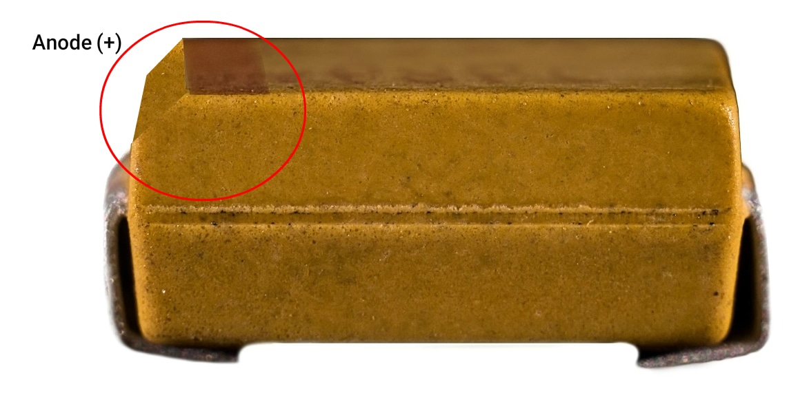
- SMD capacitors have a line on the side to indicate a terminal. However, while the line on diodes marks the cathode, the line on capacitors with a chamfered edge indicates the anode.
Note: Ensure the negative lead of the capacitor is placed in the filled area of the capacitor silkscreen on the board.

Non-polarized capacitors have no specified positive or negative terminals. You can connect them in any orientation on a PCB. Examples of non-polarized capacitors include ceramic, film (polymer, plastic), mica, and glass capacitors.
Sierra Circuits provides PCB component management services to procure and store parts to avoid risks associated with handling and counterfeits.
Check out PCB component sourcing and stocking to learn more.
ICs
ICs have multiple rows of pins and a notch or etched dot. The notch indicates the pin 1 of the IC. Other pins are numbered counterclockwise around the chip, as shown in the image below.

Batteries
Batteries come with positive and negative markings. The metal folded side indicates the positive terminal.
Power supplies
They come with standard connectors, which indicate the polarity itself. You can use diodes and MOSFETs for protection against reverse power supply polarity.
Accurate component orientation and polarity are essential for PCB functionality. Polarized components, such as diodes, LEDs, and capacitors, require specific connections to function correctly. Clear silkscreen markings, adherence to IPC standards, and following best practices for component placement can prevent assembly errors and ensure optimal performance.


