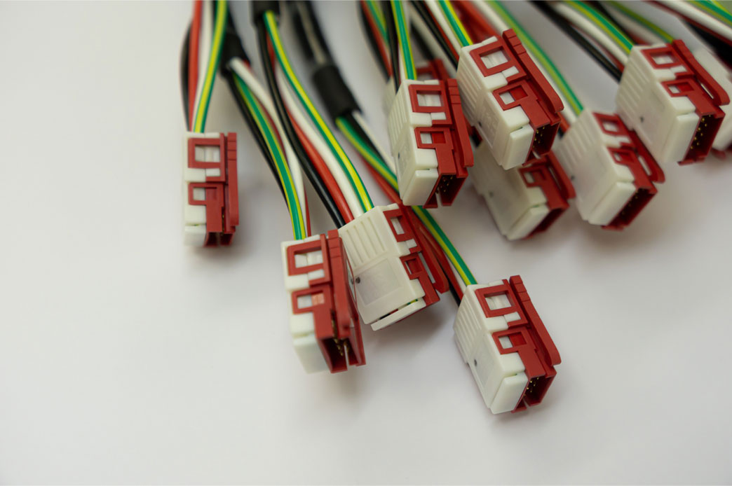
Electronic products include assembled PCBs, enclosures, and cable assemblies connecting their different parts. USB, Ethernet, CAN bus, and RF assemblies have cables and connectors. Many cables in a product are bound together to form harnesses. Harnesses are common in cars and industrial control systems. Power and signal cables are harnessed separately to avoid interference between them.
From a cable assembly standpoint, as a designer, you need to choose the readily available components. This practice reduces preproduction and production lead times. It also provides insights between cost and performance trade-offs so that you could take quick PCB design-related decisions.
Power cables typically have the cables and connectors or lugs as terminations. In power cables, the power and current ratings are important. And the wire gauge will depend on the current.
For instance, 5 V is given at one end of the cable, which carries a current of 1 A and has a resistance of 1 ohm. The voltage drop across the cable will be 1 V. Therefore, at the other end, the voltage seen will be 5-1, equivalent to 4 V. This may not be acceptable in most applications; the power loss in the cable will be 1 W. To reduce the voltage drop and power loss, the cross-sectional area of the cable should be increased to reduce the resistance. The resistance of power cables should be typically in milliohms.
An example of a communication cable is a USB cable. The parameters of a communication cable include the operating frequency, the cable impedance (typically either 50 or 90 ohms), types of shielding and whether the cable is twisted or untwisted, and types of connectors.
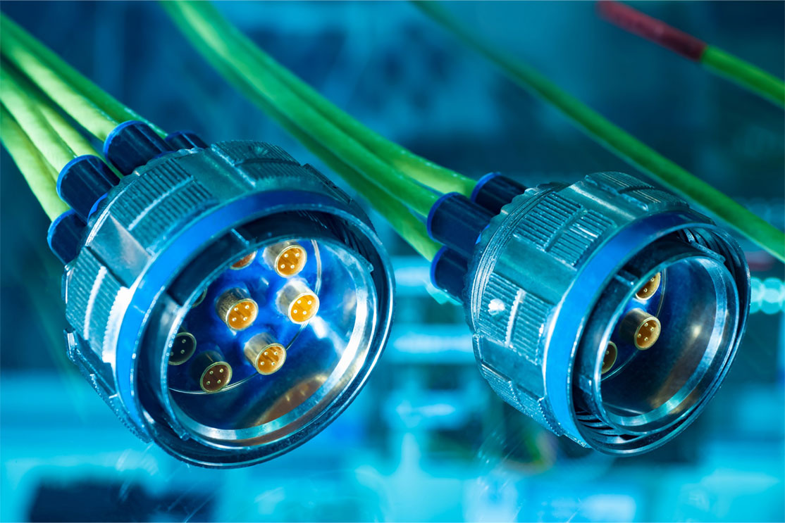
What is a cable assembly?
A cable assembly is a bunch of wires or cables grouped by a heavy-duty thermoplastic, thermoplastic rubber, or vinyl material sheath. Every cable assembly is shielded by a sheath material such as PVC, fluorocarbons, and elastomers to protect the operating environment. It also makes it more organized when in use. Cable assemblies typically have connectors at each end of the cable.

PCB Design for Assembly Handbook
6 Chapters - 50 Pages - 70 Minute ReadWhat's Inside:
- Recommended layout for components
- Common PCB assembly defects
- Factors that impact the cost of the PCB assembly, including:
- Component packages
- Board assembly volumes
Download Now
What’s the purpose of a cable assembly?
Cable assemblies are built to shield the interior wires or cables from heat, friction, moisture, abrasion, compression, etc. They are available in different shapes and sizes and designed based on the operating environment.
Specifications for a cable assembly
- Operating frequency: Operating frequency depends upon the cable size. A larger diameter cable will not support high frequencies but a small diameter cable will.
- Current and voltage rating: The voltage and current ratings of a cable assembly indicate its operating range.
- Voltage drop: A voltage drop occurs when the voltage at the end of a cable is lower than that at the beginning. It happens due to increased resistance in a circuit and can be reduced by increasing the diameter of a cable.
- Insulation material: Insulation material surrounds the individual conductor wires. It aims to protect wires from mechanical stress and prevent shorts and dielectric breakdown from nearby electrical signals.
- Insertion loss: It should be as low as possible because it indicates the ability to carry an RF signal efficiently.
- American wire gauge (AWG): AWG is the US standard for measuring the diameter of electrical conductors. AWG gives the estimation of the current-carrying capacity of the wire. The higher the AWG, the thinner the wire will be.
- Temperature rating: Temperature variations always affect the electrical performance of the cable assembly. High temperature increases the conductor resistivity leading to copper losses. Temperature changes also affect dielectric properties. That is why dielectric is usually the temperature-limiting factor (for Polyethylene, the temperature range is -65 ºC to +80 ºC and for PTFE, it is -75 ºC to +250 ºC). For extended applications above 150 ºC, solid Teflon cables are not recommended.
- Flammability rating: Materials with good flammability values help to minimize the number of toxins released during short circuits.
- Ingress protection (IP) rating: IP rating gives the acceptable measurement against obtrusion of solids and liquids into mechanical and electrical enclosures. A higher IP rating indicates better protection against water and other invasive elements.
- Voltage standing wave ratio (VSWR): VSWR should be as low as possible. It indicates uniformity along the length of a cable, connection strength, and compensation in the connectors for transitions in the cable or connector interfaces.
- Average power handling: It is related to the ability of the cable assembly to dissipate heat generated by resistive and dielectric losses. It is good to have high power handling.
- Outgassing: It occurs when trapped gas is released in PCB. This is a matter of concern in outer space where low outgassing materials are required to maintain a clean environment.
Selection parameters for a cable assembly
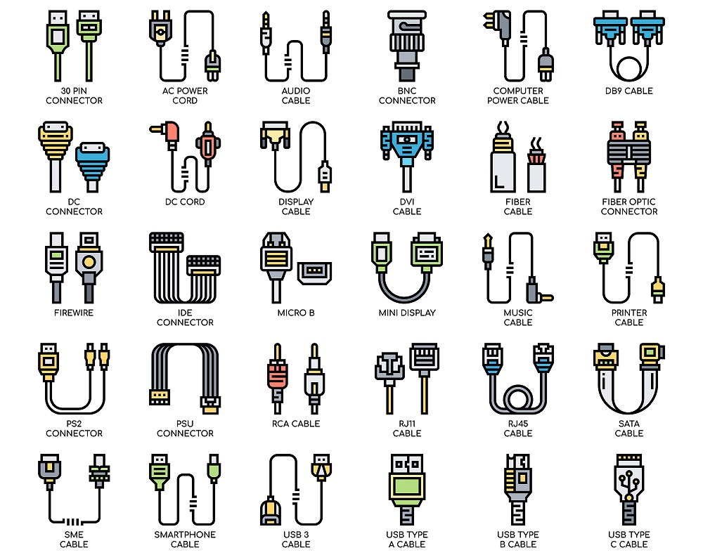
- Cable type: When selecting a cable type, review your application’s requirements based on usage and environmental conditions (extreme or even hazardous). For instance, the cable type for an assembly in a military vehicle application will be different from the cable type required in a television studio. Likewise, consider the number of conductors needed and the wire gauges to support the system functionality. A cable can be of two types: signal-carrying and power cables.
- Connector type: After selecting the cable, pick the connector type that works best for your application. Again, consider the environment and usage. Simplify this choice by communicating with a vendor who also assembles connectors and offers a variety of options from the top manufacturers. A connector distributor along with cable design and assembly capabilities is a good choice since they will provide a custom end-to-end solution that has been derived from years of experience.
- Shielding: EMI caused by noise generated by nearby cables and electronics is responsible for disrupted connections. Communication should be intact even when equipment is handled roughly, and shielding provides that type of protection. Foil shielding offers EMI protection but tears easily, making it undesirable for extreme conditions. Braiding is another option. It is far more durable, allowing easy passage of the signal.
- Overmold or cable clamp or heat shrink wrap: Overmold and cable clamps are used to secure connectors and cable junctions. They provide strain relief between the connectors and the cables. A cable clamp is a very basic option but heat shrink is the best. The heat shrink is applied over the connection area and is shrunk to provide a tight fit. It offers moderate strain relief protection and helps with moisture resistance. On the other hand, overmold is a lightweight and heavy-duty molded cover that provides the best strain relief. It is good to choose a vendor that performs overmolding in-house for the quickest turnaround time and quality.
- Coupling mechanism: Threaded connectors offer a secure mated connection. Push-together connectors can be mated and unmated easily but generally aren’t as rugged as desired. Bayonet-style connectors ensure the proper alignment of the mating halves.
- Quality: IPC-A-610, IPC/WHMA A-620 class 3, and UL certifications are essential. Follow the relevant certifications and standards concerning your region.
- DFM: Lead times tend to change based on product availability, design complexity, and application requirements. Vendors with readily available components, custom design expertise, and specification-based assembly provide the fastest delivery. But along with quick delivery, choose a certified and trusted vendor.
Quick design tips for a cable assembly
Achieving strength and durability at the same time is an intense design challenge when working in a confined environment like a cable assembly. Issues could be inaccurate design, material incompatibility, connector mating, and many more. Some of the best design methods for cable assembly are listed below.
- The wire bend radius should be as large as possible. Tight radiuses slow down the manufacturing process, inducing stress on the terminals inside the connectors, hence latent failures.
- Always identify the UL style. It helps to figure out the wire flammability value.
- Make room for dimensional tolerances. Specify all dimensions from the connector reference plane.
- Always add plating (tin, silver, nickel) to the wire to avoid corrosion and oxidation. Plating is also suitable for high-frequency operations.
- Avoid direct marking; use shrink tube markers or self-laminating labels.
- Always specify the number of contacts.
- Use screws to stick to the assembly.
- A well-defined coupling mechanism is necessary.
Every application comes with unique requirements, and a single cable assembly cannot fulfill all of them. Choose a vendor who will help you sail through these impactful decisions.


