Contents

On-demand webinar
How Good is My Shield? An Introduction to Transfer Impedance and Shielding Effectiveness
by Karen Burnham
FR4 is the most common grade of dielectric material used in the fabrication of circuit boards. It is incorporated into single-sided, double-sided, and multi-layered boards.
Here are a few qualities of FR4 materials that make them popular:
- Wide range of operating temperatures (50°C to 115°C)
- Higher Tg value (about 180°C)
- Offers decent mechanical properties to maintain board structure integrity
- Cost-friendly when compared to other materials
What does FR4 stand for?

FR stands for flame retardant, and the number ‘4′ indicates woven glass-reinforced epoxy resin. The characteristics of FR4 vary significantly depending on the manufacturer, although it is commonly known for its mechanical strength and water resistance.
This material performs as an insulator in PCBs by isolating adjacent copper planes while also providing overall mechanical strength.
What are the properties of FR4 substrate?
Flame retardant
Chemicals that are applied to materials to prevent or delay the spread of fire are known as flame retardants. FR4 substrates have excellent thermal, mechanical, and electrical properties making them a perfect choice for a wide range of electronic applications.
Flame retardant laminates and prepregs are extremely versatile, adaptable to a variety of manufacturing procedures, and produce predictable results.
Good electrical properties
The electrical properties of a PCB material are critical for signal integrity and impedance considerations. They specify how fast an electrical signal propagates through the material and how much electrical charge it can retain in a given volume. The table below lists a few important electrical properties along with their typical values.
| Electrical property | Typical value |
|---|---|
| Dielectric constant (Dk) | 5 at 1MHz |
| Electrical strength | 800 to 1800volts/mil |
| Dissipation factor (Df) | 0.009 at 1MHz |
| Surface resistivity (ρS) (Ohm/square unit) | 105 to 1010 |
The given values can vary depending on the manufacturer. For example, FR4 has a dielectric constant that varies between 3.8 and 4.8 depending on the glass weaving style, thickness, and resin content.
Low moisture absorption
Moisture absorption is the ability of a PCB material to resist water absorption when immersed in water. It is given by a percentage increase in the weight of a circuit board material due to water absorption under controlled conditions. FR4 materials offer a low moisture absorption of 0.10% when immersed in water for 24 hours.
FR4 material properties of various manufacturers
| Manufacturer and Name | Glass transition temperature (Tg) (°C) | Decomposition temperature (Td) (°C) | Dielectric constant (Dk) @ 10GHz | Dissipation factor (Df) @ 10 GHz | Moisture absorption (%) | Application area |
|---|---|---|---|---|---|---|
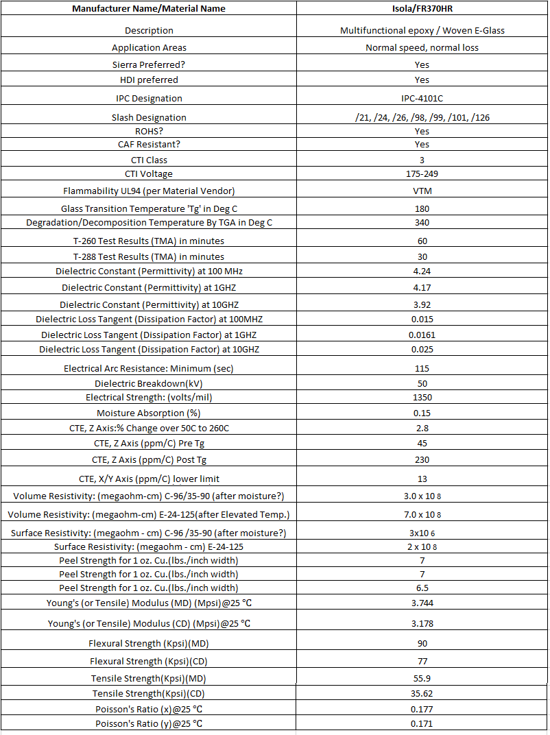
| Isola - 370 HR | 180 | 340 | 3.92 | 0.025 | 0.15 | Normal speed, Normal Loss |
| Isola - FR408HR | 200 | 360 | 3.65 | 0.0095 | 0.15 | High Speed, Low Loss |
| Nelco - N4000-13 | 210 | 350 | 3.6 | 0.009 | 0.1 | Medium Speed, Low Loss |
| Nelco - N4000-13SI | 210 | 350 | 3.2 | 0.008 | 0.1 | Medium Speed, Low Loss |
| Ventec - VT-47 | 170 | 340 | 4.27 | 0.016 | 0.12 | Normal speed, Normal Loss |
Datasheet of Isola 370HR
Limitations of FR4 circuit board materials
FR4 has been used in the production of printed circuit boards for many years now. It’s inexpensive and provides adequate electrical insulation. However, when FR4 is used in high-speed applications, the following problems may occur:
Insulating stability
Although FR4 is a great insulator, it has its limits when subjected to high power, voltage, or heat. If certain limits are exceeded, the materials’ insulating properties will deteriorate, and they will begin to conduct electricity instead. This causes circuit board failures.
Controlled impedance
FR4 does not offer uniform dielectric constant like high-speed board materials. As the frequency goes up the Dk varies. Dielectric constant tolerances for high-speed materials are less than 2%, whereas for FR4 it is up to 10%.
Dk variations in FR4 impose challenges while maintaining impedance values. Hence, this material is not a preferred choice for controlled impedance boards.
Signal losses
Signal loss is an important aspect of PCB design, particularly in high-frequency applications. FR4 isn’t the best material for these applications since it has a greater Df (dissipation factor) than high-frequency materials.
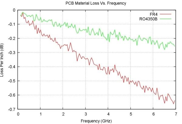
FR4 has a Df of around 0.020, while most high-frequency laminates have a Df of around 0.004, which is a fourth of FR4’s Df. The smaller the Df, the lesser the overall signal loss.
One more drawback is that the Df of FR4 increases as the frequency of a signal increases. As a result, these PCBs suffer higher signal losses than a board built using a high-frequency laminate. The graph above plots the frequency vs. loss per inch (dB) of FR4 and Rogers RO4350B (high-speed material). It clearly depicts that the FR4 material suffers a greater loss at high frequencies.

High-Speed PCB Design Guide
8 Chapters - 115 Pages - 150 Minute ReadWhat's Inside:
- Explanations of signal integrity issues
- Understanding transmission lines and controlled impedance
- Selection process of high-speed PCB materials
- High-speed layout guidelines
Download Now
Tips for selecting the right FR4 material
While choosing FR4 material, it’s critical to consider the thickness and other important characteristics of the laminate.
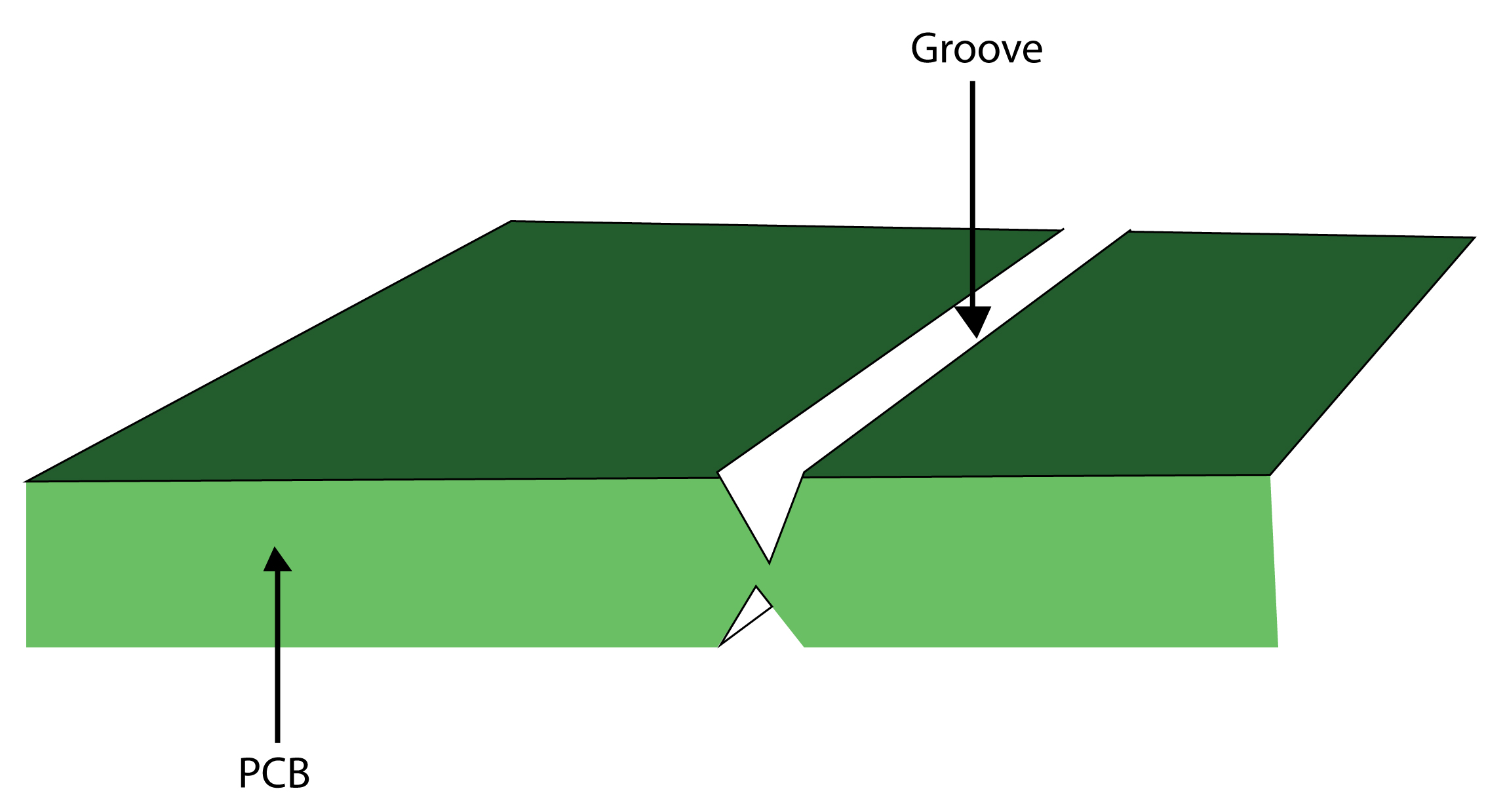
- Avoid using thinner materials for circuit boards with grooves.
- Choose a high-performance FR4 laminate if the operating temperature of the application exceeds 150 °C. These materials have better thermal performance and low expansion rates when compared to standard FR4 while retaining the same manufacturability. Isola 370HR is an example of a high-performance FR4 material.
- Select a dielectric material that offers a uniform dielectric constant (Dk) over a wide range of frequencies. The parasitic capacitance between a trace and its reference conductor, or between a trace and any other nearby conductors, will be affected by dielectric constant variations.
IPC-A-600 standard for FR4 materials
FR4 PCBs are made up of a square grid glass strands woven together. This sheet of woven glass is impregnated with epoxy resin and semi-cured to make a ply of prepreg. We discuss the IPC-A-600 or IPC-6012 standard related to base materials in the following section.
Standards related to the base material surface
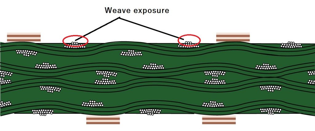
Weave exposure
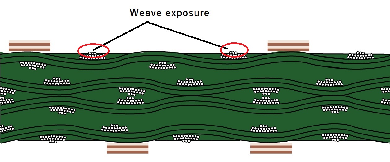
It is the state of the material in which unbroken woven cloth fibers on the surface are not entirely covered by resin, as shown in the image above.
Weave exposure is acceptable in all classes (class 1, 2, and 3 boards), provided that the remaining space between conductors meets the minimum spacing requirement. For more about class 2 and class 3 boards, read IPC class 2 vs. class 3.
Weave texture
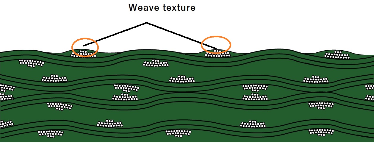
It is a condition in which the weave pattern is clearly visible on the surface, but the fibers of woven cloth are fully covered in resin, as seen in the image above. Weave texture is permissible in all classes; however, because of their similar appearances, it is commonly confused with weave exposure.
To learn more about PCB materials, check out our PCB material design guide.
PCB Material Design Guide
9 Chapters - 30 Pages - 40 Minute ReadWhat's Inside:
- Basic properties of the dielectric material to be considered
- Signal loss in PCB substrates
- Copper foil selection
- Key considerations for choosing PCB materials
Download Now
Standards related to base material subsurface
This section describes the subsurface conditions of laminated materials that are externally visible. Measling, crazing, delamination/blistering, and foreign materials are some of the most common subsurface base material conditions.
Measling
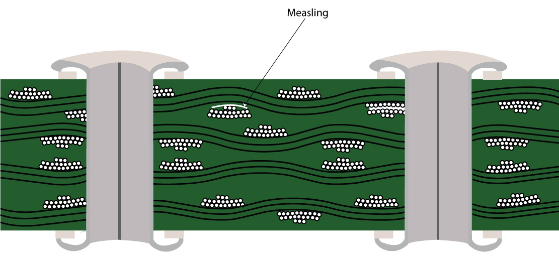
The presence of discrete white spots in the base material of a PCB is known as measling. Measling develops when the resin is not optimally applied to the board during the lamination process. Measles are permissible in all applications except for high-voltage products. However, excessive measling might decrease the board’s electrical and overall performance.
Crazing
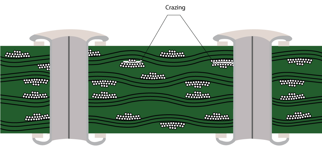
It is a phenomenon wherein a series of connected white spots or crosses appear in the base material indicating the separation of glass cloth fibers and connecting weave junctions.
Class 1 acceptability:
- The space between conductive patterns should not be less than the minimum conductor spacing.
Class 2 and 3 acceptability:
- Same as class 1 acceptability.
- The distance between adjacent crazing patterns should not be more than 50% of the distance between adjacent conductive patterns.
- Crazing at the board’s edge has no effect on the minimum distance between the board’s edge and the conductive pattern.
Delamination/Blister
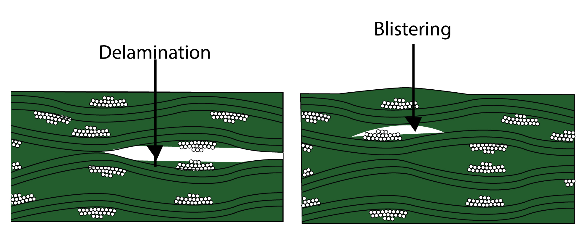
Any planar separation on a circuit board, such as between plies inside a base material, or between material and conductive foil is termed as delamination. Delamination characterized by localized swelling is termed as a blister.
Class 1 acceptability:
- The area of the board affected by delamination does not exceed 1% of the total area.
- The blister or delamination should be less than 25% of the distance between conductors.
- Delamination should not be closer to the edge of the board.
Class 2 and 3 acceptability:
- Same as class 1 acceptability.
- The space between conductive patterns should not be less than the minimum conductor spacing.
Foreign materials
Foreign materials can be detected in raw (B-stage) laminate. They can be either conductive or non-conductive. Translucent particles trapped inside the PCB are permissible in all classes, provided that the electrical and thermal properties of the board are not affected.
FR4 is the most commonly used material in PCB manufacturing. These boards are durable, water-resistant, and provide excellent insulation between copper layers, reducing interference and ensuring signal integrity. However, FR4 is not the greatest material to utilize in the boards operating at high frequencies or in harsh situations.
Have queries regarding FR board materials? Post them on our forum, SierraConnect. Our design experts will resolve them.






Start the discussion at sierraconnect.protoexpress.com