What is a UL rating?
UL rating suggests that a product or machinery is UL certified and fulfills specified safety and operability measures for customers and manufacturers. This certification is done by Underwriters Laboratories, which is a third-party company founded in Chicago.
This standard is for testing products before they are released into the market and also for setting industry standards for manufacturing.
Is UL certification important?
This certification is very important because it is issued by a safety organization that sets industry standards for manufacturing products. Hence all the process stages for manufacture have to be performed under this standard. This ensures the safety of the manufacturing process.
The organization also tests products to verify that they meet the required standards. For example, it tests a particular electronic product to see if it can handle the specified amount of current or voltage.
Difference between UL listed and recognized
In general, the organization certifies in two categories, UL listed and UL recognized. The recognition category deals with the machinery and parts that are involved in the production of products. Hence it has more to do with the manufacturer than the customer. The listed certification is meant for stand-alone products and therefore is more familiar amongst customers.
Sierra Circuits is proud to serve those who serve.
That’s why every mil-spec PCB we manufacture receives priority scheduling for fast-track production. Learn more about our experience designing PCBs for the military and aerospace industry.
What is the difference between CE and UL ratings?
CE rating is associated with an organization called Comformité Européenne. This organization sets standards for common electronic devices in Europe. Hence products that are going in the markets of Europe are mostly recognized under this standard. The CE rating confirms that the product complies with the European Union’s (EU) new directives like RoHS and many others.
Underwriters Laboratories standard for PCBs
In the case of circuit boards, this certification guarantees the customer that the board they are getting will be able to handle the parameters specified. It also ensures that the PCB manufacturing is done as per the UL-recognized industry standards.
The UL 796 is the standard for tests and safety of printed wiring boards. All the circuit boards manufactured at Sierra are tested based on this safety standard. Apart from this, CAN/CSA-C22.2, a safety standard for the evaluation of the standards of polymeric materials also forms a basis for testing at our facility.

PCB Material Design Guide
9 Chapters - 30 Pages - 40 Minute ReadWhat's Inside:
- Basic properties of the dielectric material to be considered
- Signal loss in PCB substrates
- Copper foil selection
- Key considerations for choosing PCB materials
Download Now
What is the UL fire rating?
The individual PCBs are also tested against the UL-94 flammability standards. This standard identifies plastics in different classes according to how they burn in different orientations. These classes include V0, V1, V2, HB, 5VB, and 5VA. For example, FR4 should come under the UL-94 flame class of V0.
Base material standards
An example record showing the testing of base materials is given below:
| Type | Base material | Minimum thickness (mm) | Minimum copper thickness (mics) | SS/DS | PWB manufacturing process | Meets UL 746E DSR | CTI V (PLC) | ||
| UL/ANSI grade | Manufacturer | Grade | |||||||
| D2 | FR-4.0 | I | PCL-FR-370HR, PCL-FR-370
Turbo-0 |
0.38 | 17 | DS | J | Yes | 175 (3) |
| D2 | FR-4.0 | I | FR-408 | 0.38 | 17 | DS | J | Yes | 175 (3) |
| D2 | FR-4.0 | I | FR-408HR | 0.48 | 17 | DS | J | Yes | 175 (3) |
| D2 | FR-4.0 | IT | IT-180ATC | 0.38 | 17 | DS | J | Yes | 175 (3) |
The base material is tested for its minimum thickness, minimum copper thickness, and then whether they meet the UL-796 standard or not. These materials are also checked for their comparative tracking index (CTI) , that is the voltage difference at which the insulation of the given material may break down.
Based on the breakdown voltages, materials are divided into the following categories.
These break-down voltages are divided into 6 categories with 0 as the highest for voltages of 600V and higher. The lowest category is 5 for voltages less than 100V. FR4 comes in category 3 as it has a CTI ranging from 175V to 249V. The table below shows the categorization based on the CTI values.
| CTI (in Volts) | Class |
| CTI ≥ 600V | I |
| 600 > CTI ≥ 400 | II |
| 400 > CTI≥ 175 | IIIA |
| 175 > CTI ≥ 100 | IIIB |
UL standards for spacing between traces at different working voltages
The spacing between the traces in a PCB should be such that there is no flashover or short-circuit between them. Hence the distance will always depend on the applied voltage and while designing them, the withstanding voltage should be known.
As per UL 796, the specified withstanding voltage between two conducting traces is equal to 40V/mil or 1.6kV/mm. These standard spacings with reference to the UL or IEC specifications are always more than what is needed for the ordinary operation of the board. It is to ensure additional electric shock protection.
If this additional protection to electric shock is not required and only functional isolation is enough, then UL 60950-1 provides some relief to this value. This standard allows the use of distances lesser than those mentioned in the earlier standards. The only thing that should be noted here is that the reduced distance should be able to prevent short circuits or flashovers.
This is ensured by the electric strength test or the HiPot test.
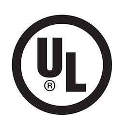
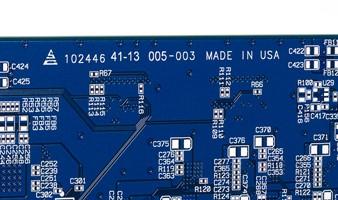
Thus, this certification on circuit boards is a matter of trust for the customers. When you see the UL-certified logo on a PCB, it guarantees that the board has been manufactured under the safety standards laid down by Underwriters Laboratories.
Get started designing your military grade PCBs
We design, manufacture and assemble IPC Class 3A circuit boards in just 2 days for standard boards. Our PCB experts and engineers are available to guide you through the design and manufacturing process, while delivering all the traceability and tolerance documents you need.
Start building your quote now.


