


Contents
CAN bus establishes efficient communication links among microcontrollers through a twisted pair of cables without involving a host computer.
The architecture guarantees efficient signal transmission even in harsh environments with high temperatures and vibrations. This feature makes it an ideal choice for automotive designs. Earlier vehicles had crammed point-to-point wiring systems for data communication. With the advent of new cutting-edge features, it became challenging for engineers to incorporate them using a standard communication model due to the increase in circuit complexity.
One way to deal with this hurdle is by incorporating the CAN bus technology, which eases serial communication while reducing the cost and complexity of the board.
What is CAN bus?
CAN bus is a multi-node, bidirectional serial bus that is widely used in the automotive industry. It broadcasts small messages to the whole network within a concise span through a two-wire bus. The bus operates in a priority-driven fashion when distributed control needs to be achieved. The amazing thing is that communication through the CAN bus does not require any host computer and has supremacy in detecting faults. This lossless high-speed protocol incorporates bitwise transmission, thus reducing the risk of congestion on the buses.

High-Speed PCB Design Guide
8 Chapters - 115 Pages - 150 Minute ReadWhat's Inside:
- Explanations of signal integrity issues
- Understanding transmission lines and controlled impedance
- Selection process of high-speed PCB materials
- High-speed layout guidelines
Download Now
Standards to design a CAN bus
ISO 11898
This standard states that the CAN bus operates on the open systems interconnection (OSI) model, which comprises 7 layers:
- Physical layer
- Data link layer
- Network layer
- Transport layer
- Session layer
- Presentation layer
- Application layer
The communication in the CAN bus network is defined by physical and data link layers.
ISO 11898-1
It specifies the standards for the CAN bus data link layer. It consists of features that are required to set up an interchange of digital information between modules involving the CAN data link layer.
ISO 11898-2
This paradigm defines the requirements of the physical layer. The layer describes the standards for cable types, electrical signal levels, node requirements, and impedance. ISO 11898-2 sets forth the attributes as follows:
- Baud rate: The nodes should be linked through a two-wire bus with baud rates up to 1 Mbps (classical CAN) or 5 Mbps (CAN FD).
- Cable length: Maximum cable lengths for CAN must be between 500 meters (125 kbps) and 40 meters (1 Mbps).
- Termination: CAN bus must be provided with a 120Ω termination resistor at each end of the bus to ensure proper termination.
ISO 16845
This ensures CAN bus specifications are in compliance with ISO 11898 by setting up a test plan.

An overview of the CAN layout
CAN bus is an uncomplicated, robust network protocol with a high data transfer rate. The standard sets the seal that no data will be lost and avoids message collision. The ingenious layout also guarantees the prolonged lifetime of the system. In the upcoming section, you will learn the fundamentals of CAN layout.
Electronic control units or nodes
Devices connected to the CAN bus line are defined as electronic control units or nodes. The CAN network needs two or more ECUs for communication to be enabled. The number of nodes required depends on the complexity of the circuit, i.e., whether it is a simple I/O device or an embedded system with a CAN interface. All the ECUs are connected through a two-wire bus.
Each node comprises a CPU, a CAN controller, and a transceiver. The parallel arrangement of all CPUs keeps the node synchronized and samples all data simultaneously. The primary function of the CAN controller is to establish connections among all nodes and convert digital information on the bus into messages.
According to ISO 11898-1, the transceiver establishes a link with the physical layer. Physical layers such as high-speed and low-speed CANs demand different kinds of transceivers. These transceivers adjust the signal level of sent and received data at a particular node. These nodes communicate with each other through the network. All the nodes can send and receive data, but not simultaneously.
CAN bus line
The physical layer of a CAN bus network defines the fundamental communication between the devices connected to it. In a CAN bus system, there are two twisted wires, CAN_H and CAN_L. CAN_H handles the higher, and CAN_L drives the lower signal communication.
They are considered differential pairs and carry the same voltage in the idle mode of a network. During transmission, the CAN_H line possesses a higher voltage than the CAN_L line. CAN bus communication is set up by the generated differential voltage between the CAN bus lines. In addition, this layout ensures immunity to inductive spikes, electric fields, and other disturbances.
Differential Pair eBook
3 Chapters - 18 Pages - 30 Minute ReadWhat's Inside:
- Differential and common mode signals
- Differential impedance
- Even and common modes
- The physical parameters
Download Now
Can bus line termination
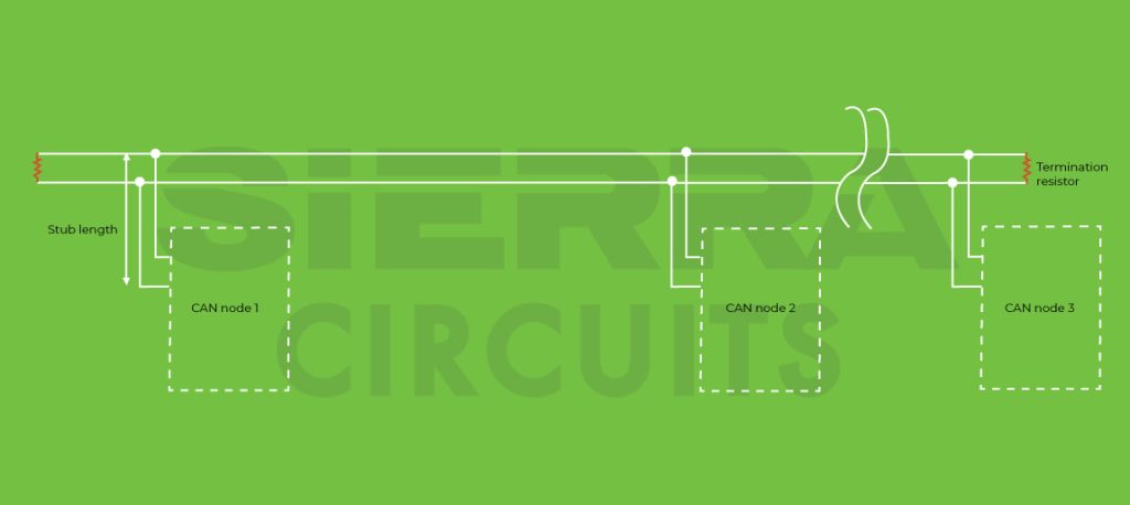
A CAN bus line must be terminated by proper resistors. These resistors help to prevent electrical reflections on the bus and ensure the bus gets the correct DC levels. The value of the termination resistor depends on the number of nodes present in the network. Usually, the range varies from 100 to 130Ω.
PCB design tips for a reliable CAN bus
The CAN bus is vital when designing a board for automobile communication. The superiority of the protocol lies in its benefits of reduced wired connections and the reduced risk of message collisions. To ensure the best performance of your PCB, follow the guidelines listed below:
Incorporate a circuit protection component
CAN bus circuitry is well-suited to operate in harsh environments. This feature necessitates the addition of a circuit protection unit, such as a TVS diode. This protective component carries the generated surges to the ground and prevents the transceiver from getting damaged.
Reduce the length between the transceiver and the connector
It is advisable to shorten the cable length between the transceiver and connector as much as possible to mitigate the risk of impedance discontinuity.
Route CAN bus signals in parallel
While designing the layout, make sure CAN bus signals are routed parallelly over the traces having the same length. This helps to eliminate the electrical and electromagnetic interference that could corrupt the transmitting data.
How does CAN operate?
CAN messaging offers transferring data in a frame. The four types of frames are listed below:
Data frames
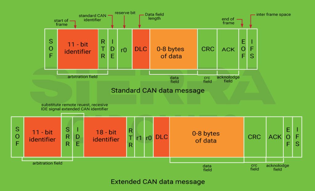
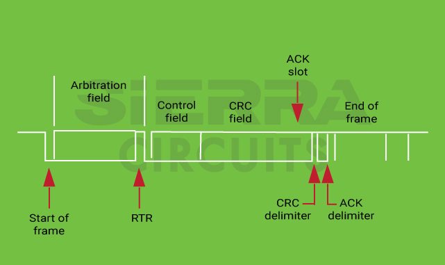
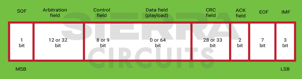
Data frames are used to transfer data from one node to another or between multiple nodes. It consists of the following significant fragments:
- CAN data is classified into two types based on their length: standard (2.0A) and extended (2.0B). For the extended one, an additional 18-bit identifier is added in the arbitration field.
- The arbitration field decides the priority when more than one node holds messages for the bus. This field comprises:
- CAN 2.0A: An 11-bit identifier and the RTR bit
- For CAN 2.0B: A 29-bit (11-bit + 18-bit) identifier and the RTR bit
- Data field that contains 0 to 8 bytes of information.
- The CRC field consists of a 15-bit checksum that is used for error detection.
- An acknowledgment slot is used when the CAN controller correctly receives the message and sends an acknowledgment bit at the end of each message. The transmitter validates the bit and retransmits the message if no acknowledgment is perceived.

- The arbitration field consists of the message identification number and the remote transmission request (RTR) bit. With increasing priority, the messages get lower ID numbers. If multiple nodes contend with data at the same time, the lowest message id obtains priority through an arbitration process. RTR bit ensures the transmission of data.
Remote frames
It is used to solicit data from other nodes. As an example, if node A transmits a remote frame with the arbitration field 234, then node B might get back with a data frame with the arbitration field set to 234 as well. RTR bit holds the highest dominance here. There is no data field present in the remote frame.
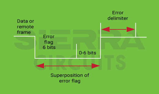
Error frames
It is transmitted when a node determines an error and informs other nodes to check for the same. If a fault is detected, an error message is conveyed. The transmitter will then automatically retry to transfer the message. The error frame comprises an error flag of 6 bits and an error delimiter, which is 8 recessive bits. The error delimiter offers some space in which the other nodes on the bus can send their error flags.
Overload frames
The overload frame reports the overload condition. Similar to the error frame, it is transmitted by a node that becomes stuck with multiple tasks.
History and development of the CAN protocol
The controller area network was initially developed in the mid-’80s by a German company, Bosch. Gradually, the standard has been facing several advancements. In 1986, SAE International accepted the protocol. Intel produced the first CAN controller chip, the Intel 82526, in 1987. Later, Philips also manufactured the Philips 82C200. The CAN 2.0 application was marketed in 1991 by the inventor’s company.
Two years later, the International Organization of Standardization finally released ISO-11898, mentioning CAN standard specifications. These include CAN voltage, connector interface, and other physical standards. such as ISO-11898-1, which is structured for the data link layer, and ISO-11898-2, which is the physical layer for high-speed CAN.
Different kinds of high-level protocols, such as CANopen and DeviceNet, have been developed. Payload and low data transfer rate solutions were developed using CAN with a flexible data rate (CAN FD). With a 5 Mbps bit rate and 64-byte payload, CAN FD is highly acceptable in commercial sectors now.
CAN XL is a recent development with a 10 Mbps speed exceeding its predecessor, CAN FD. CAN XL offers superior safety, data rate, payload, robustness, and arbitration. It can support complicated network topologies and get upgraded accordingly. The noticeable thing is that CAN XL can be implemented with CAN FD, and a mixed network can be generated.
Different types of CAN bus
As per the ISO 11898 standard, multiple versions of the CAN bus can be defined. The significant ones are explained in this section.
Low-speed CAN
The low-speed CAN protocol is effective at detecting faults. The maximum data transfer rate supported is 125 kbps, which confirms economical wiring. This protocol is implemented in the display, diagnostics, dashboard control, and power windows of automobiles.
High-speed CAN
High-speed CAN is used in critical subsystems that demand high data accuracy. Most frequently, it is used in airbags, anti-lock braking systems, electronic stability control, and engine control units. The protocol can support data transfer rates from 1Kbps to 1Mbps.
CAN FD
The bandwidth requirements of modern technologies are growing by the day. The latest version, CAN FD, offers a flexible data rate with more data per message and higher speed. A standard CAN provides 8 bytes of data length. But with CAN FD, you can get 800% more, i.e., 64 bytes of data. The maximum data rate can also be increased from 1 Mbps. Now, it is crystal clear why CAN FD becomes the first choice for automobile OEMs.
Comparison between CAN bus and USB/Ethernet
- CAN establishes distributed communication similar to USB and Ethernet.
- Both USB and Ethernet convey data from source to destination using a point-to-point protocol. The CAN messaging service does not support point-to-point wiring.
- Unlike USB and Ethernet, the CAN protocol operates without host computer support. The devices connected to the CAN network can send and receive messages through a twisted-pair cable.
Advantages of CAN bus
The CAN bus protocol ensures reliable data transfer with the low-level network. Below are the key benefits that make the standard widely accepted:
Inexpensive microchip
The physical and data link layers can be incorporated in low-cost microchips in several kinds of configurations.
Robust towards interferences
It safeguards complex and sensitive circuitries from electrical and electromagnetic disturbances. Hence, it is appropriate for critical designs such as automobiles and medtech.
Fault detection ability
The CAN bus is capable of detecting errors before transmitting data to the desired address.
Centralized network
Enables data logging with efficient communication among all ECUs in the network.
Prioritized communication
CAN frames are given specific priority codes. The highest priority data obtains immediate bus access without interrupting the other frames.
Less complex and costly
Establishes a communication channel through a single network instead of heavy electrical wiring, thus reducing weight, complexity, and overall cost.
Areas of application of CAN bus
Initially, the idea of the CAN bus emerged for the development of automobile communications. Now, the protocol is widely used in various low-bandwidth industrial applications. Here are a few sectors where you can see applications of the CAN bus:
- Varieties of vehicles, including cars, motorcycles, and trucks
- Manufacturing plants
- Elevators
- Airplanes and ships
- Home appliances like washing machines and dryers
- Medical devices
CAN bus is a prevalent solution to incorporate advanced features in automobiles. With this robust protocol, you can ensure reliable data exchange. The controller area network ranks higher than other protocols with regard to cost-effectiveness and error-detecting efficiency. If you require any assistance in designing your advanced high-speed boards, let us know in the comments section. Our design experts will be happy to help you.
Need help in designing reliable PCBs? Our engineering team can help you with thermal management, stack-up design, and DFM analysis.
You can book a meeting with our experts or call us at +1 (800) 763-7503.

About Poulomi Ghosh : Poulomi is a microwave engineer specializing in EMI, EMC, RF, and high-speed electronics. As a senior technical writer at Sierra Circuits, she creates advanced engineering articles and webinars for hardware engineers and PCB designers.


