Coverlay is an insulating film used in flex PCBs to protect copper traces. It provides both mechanical protection and electrical insulation and is designed to withstand frequent bending in a dynamic environment.
In rigid printed boards, the solder mask layer provides protection and insulation. Similarly, the coverlay in flex printed circuits (FPCs) serves the same purpose.
Highlights:
- Coverlay insulates copper conductors and shields them from moisture and chemicals.
- Compared to LPI solder mask, coverlay offers higher flexibility and superior insulation.
- The choice of the coverlay depends on thermal, mechanical, and budget constraints of your design.
What are the functions of coverlay in flex PCBs?
In flex circuit board designs, coverlay:
- Insulates copper conductors to prevent short circuits.
- Protects traces from moisture, dust, and chemicals.
- Maintains durability under repeated bending and flexing.
- Provides high dielectric strength to prevent electrical breakdown.
- Acts as a protective layer during soldering.
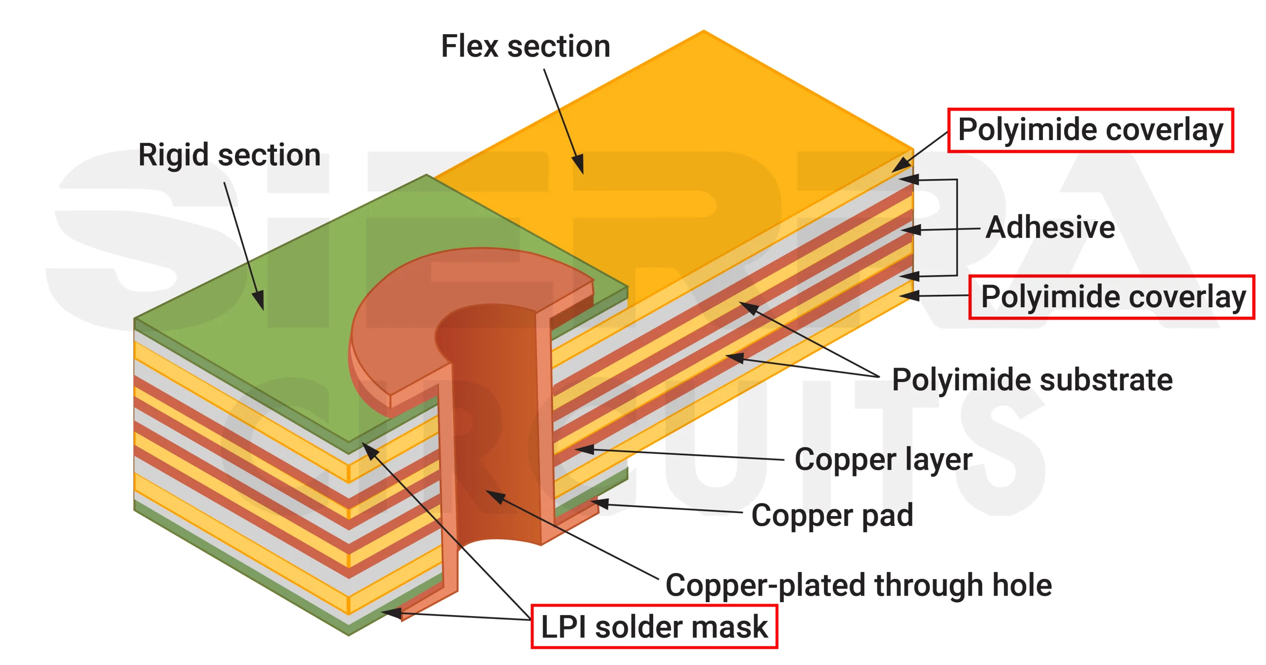
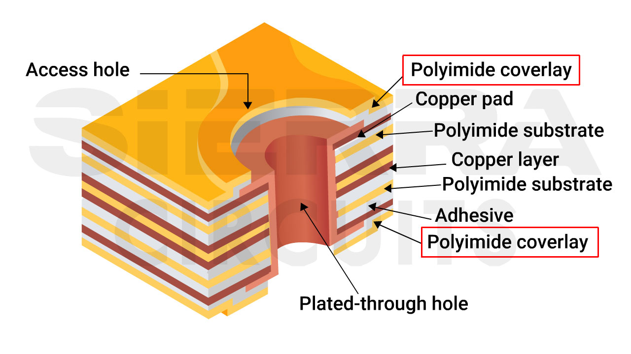
Multi-layered flex PCB stack-up with polyimide coverlay.
Unlike solder mask, typically used on rigid PCBs, coverlay is designed to withstand frequent bending, folding, and dynamic movement, making it essential for flexible circuit applications.
Coverlay vs. solder mask in circuit boards

| Parameter | Coverlay | Solder mask |
|---|---|---|
| Material | Polyimide film with adhesive | Liquid photoimageable epoxy |
| Flexibility | Excellent, withstands repeated bending | Limited, prone to cracking under stress |
| Dielectric strength | High (offers superior insulation) | Moderate (adequate for rigid applications) |
| DFM rules | Dam size ≥ 10 mil Trace-to-opening clearance ≥ 3 mil |
Dam size ≥ 4 mil Trace-to-opening clearance ≥ 4 mil |
| Processing | Requires precutting, punching, and lamination | Photoimageable; patterned with imaging/development |
| Limitations | Not suitable for fine-pitch components; possible dimensional shift during lamination | Less reliable in flex areas; registration issues at small clearances |
| Application areas | Flex sections of flex/rigid-flex PCBs (requires window or gang openings if used on the entire rigid-flex board) | Rigid PCB sections and cost-sensitive designs |
| Cost | Higher due to material cost and processing complexity | Lower due to simpler and faster processing and lower material costs |
What are the different types of coverlays in flexible PCBs?
Polyimide-based films, polyester, acrylic, epoxy, and silicone are the types of coverlays used in flex circuits. The choice depends on thermal, mechanical, and budget constraints of your design. Here’s a quick comparison:
| Coverlay material | Typical thickness | Thermal resistance | Flexibility | Chemical resistance | Cost | When to choose |
|---|---|---|---|---|---|---|
| Polyimide film + adhesive (typically epoxy or acrylic) | Film: 12.5–50 µm; Adhesive: 12.5–25 µm |
High (≥150-200°C) |
Excellent | Very good | Medium | Standard choice for most static and dynamic flex PCBs used in consumer electronics. |
| Adhesiveless polyimide | 12.5–50 µm | Excellent (≥200°C) | Excellent (better bend radius) | Excellent | Higher | Ideal for high-reliability, ultra-thin flex circuits in aerospace, automotive, and military applications. |
| Polyester (PET) | 25–50 µm | Moderate (≤120-150°C) | Good | Moderate | Low | Used in low-cost applications with minimal thermal or flexing requirements. |
| Flexible epoxy covercoat | 10–25 µm | Moderate (≤150°C) | Limited | Moderate | Low | Used in cost-sensitive prototypes requiring moderate protection but limited flexing. |
| Acrylic resin film | 25–50 µm |
Lower (≤120°C) |
Fair | Low | Low | Best for very low-cost, short-life flex circuits with minimal bending demands. |
| Silicone polymer sheet | 25–75 µm | High (≥200°C) | Very high (soft and elastic) | Very good | High |
Chosen for applications that undergo extreme vibration or mechanical stress, such as medical, sensor, and aerospace systems. |
Sierra Circuits fabricates and assembles high-performance flex PCBs engineered to withstand harsh environments and support dynamic applications.
Check out flex PCB capabilities to learn more.
Things to include in your fab notes about coverlay
PCB designers should specify the following details in their fab notes on coverlay:
- Material type and thickness: Specify the polyimide film and adhesive thickness used in the coverlay stack.
- Color: Define the desired coverlay color (e.g., amber, black, or clear).
- Openings and clearances: Indicate the dimensions and required clearance around pads, vias, and component lands.
- Adhesive type: State whether an acrylic or epoxy adhesive should be used, depending on the design’s thermal requirements.
- Layer reference: Clearly specify coverlay layers to avoid confusion during the CAM process.
Solder masks are suitable for rigid boards and low-flex areas of rigid-flex boards, but they can crack or delaminate in high-flex regions. Coverlay in flex PCBs, on the other hand, offers superior performance in flexible areas.
Download our Flex PCB Design Guide to learn more about FPCs.

Flex PCB Design Guide
10 Chapters - 39 Pages - 45 Minute ReadWhat's Inside:
- Calculating the bend radius
- Annular ring and via specifications
- Build your flex stack-up
- Controlled impedance for flex
- The fab and drawing requirements


