Does your PCBA house check for component errors?
Electronics is about transforming information into electrical signals and using the high-speed processing capabilities of electronics to perform tasks reliably, repeatedly, and fast. Electronic components and printed circuit boards form the basic parts of an electronic system.
While electronic components process information in form of electrical signals, a printed circuit board is the skeletal structure on which the electronic components are mounted and soldered to hold them together and provide pathways for information to flow between components through PCB traces.
PCB traces are metal wires connected between components. These traces are usually copper strips and sometimes aluminum or silver. The material, on which the components and traces are placed, is made of insulator material (dielectric), typically fiberglass impregnated with resin. This dielectric material can be of various kinds depending on the application of the circuit board.
Over the last few decades’ electronics technologies and product development have been growing and rapidly have become more and more complex. Knowledge of electronic components is essential to build successful electronic products.
This article gives an overview of the different types of electronic components. It focuses on the parameters to be considered while selecting an electronic component and gives details about standard sizes and shapes of components. These are essential while designing and manufacturing an electronic product. To learn about failures, read common errors encountered in discrete components.
Some of the most commonly used electronic components are resistors, capacitors, inductors, diodes, LEDs, transistors, crystals and oscillators, electromechanical components like relays and switches, ICs, and connectors. These components have leads/terminals and are available in specific standardized packages, that the designer can choose to suit his application. SMT (surface mount technology) and through-hole are the two types of mounting techniques used to place components on a PCB.

Design for Assembly Handbook
6 Chapters - 50 Pages - 70 Minute ReadWhat's Inside:
- Recommended layout for components
- Common PCB assembly defects
- Factors that impact the cost of the PCB assembly, including:
- Component packages
- Board assembly volumes
Download Now
Types of electronic devices
Electronic devices can be divided into two major kinds: Passive and Active devices based on their functionality.
Passive devices
Generally, resistors, capacitors, inductors, are specified as passive devices.
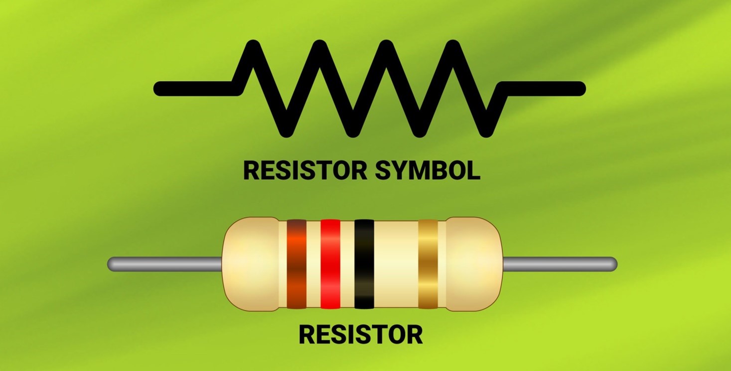
Resistors
The resistor is a passive electrical component whose function is to introduce resistance to the flow of electric current in an electrical circuit to limit the current. The magnitude of the opposition to the flow of current is called the resistance of the resistor. A larger resistance value indicates a greater opposition to current flow. The resistance is measured in ohms (Ω), and its equation is as follows.
R=V/I
The voltage (V), current (I), and resistance (R) are related by Ohm’s law. i.e. V = IR. The higher the resistance R, the lower is the current I for a given voltage V across it. It is a linear device.
Resistors dissipate electrical energy given by P=I² R Watts or Joules/sec.
Resistors are made using different materials such as carbon film, metal film, etc. However, we will concentrate on the most common varieties and their attributes.
Resistors’ values vary from milliohms to mega ohms and the tolerance of typical resistors varies from 1% to 5%. However, for precision resistor tolerance varies below 1% from 0.1% to 0.001% and hence they are more expensive and are used in analog circuits where precise/reference voltage is needed. Commonly used Resistor are available with maximum power rating of 1/8(0.125W), 1/4W (0.25W), 1/2W (0.5W), 1W, 5W. Based on the values and power ratings, SMD resistors are made in different sizes codes 1210, 1206, 0805, 0603, 0402, 0201. This also includes R-packs resistor network used for pull up /pull down for circuits interfaces.
Different types of resistors by size and form
- Through-hole resistors
- Surface-mount resistors SMD/SMT
Different types of resistors by application
- Common resistor: used in current limiter, setting biases, voltage dividers, pull up, filtering, termination resistors, load resistors, etc.
- Precision resistor for voltage feedback circuits, voltage references.
- Current sense resistors
- Power resistors
Resistor selection parameters
While selecting any resistor in the circuit, the designer needs to consider the following parameters based on the application and real-estate available on the printed circuit board.
- Resistance value(R),
- Power (Wattages) dissipated across it,
- Tolerance (+/- %)
- Size based on available space on PCB.
Resistor manufacturers: AVX, Rohm, Kemet, Vishay, Samsung, Panasonic TDK, Murata, etc.
Capacitor
The Capacitor is a passive electrical component, whose function is to store electrical energy and deliver it to the circuit when needed. The capacity of a capacitor to store electrical charge is known as the capacitance of that capacitor. It is denoted by (C). The unit of capacitance is Farad (F) and can range from, micro Farad (µF) 1x 10⁻⁶ F, Kilo pico Farad (KpF), or nano Farad (nF) 1x 10⁻⁹ F to pico Farad (pF) 1x 10-12 F. Typical values range from 1pF to 1000uF.
The various uses of capacitors are:
- It blocks the flow of DC voltage and permits the flow of AC hence used for coupling of the circuits.
- It bypasses the unwanted signal frequencies to ground.
- It is used for phase shifting and for creating time delays.
- It is also used for filtration, especially in removing ripples from the rectified waveform.
- It is used to get the tuned frequency.
- It is used as a motor starter.
Capacitor equation is given as follows;
C=Q/V
Where Q denotes charge and V denotes voltage across the capacitor and C denotes the capacitance.
Since current i=dq/dt i.e. rate of change of charge,
Hence, I = C dV/dt
Therefore, if the voltage across a capacitor is constant, there will be no current flow through the capacitor; and current will only flow across the capacitor if the voltage across it changing with time for example an AC voltage. That is why a capacitor blocks DC signals and allows only AC signals to pass through it when used in the series of the path of the signal.
The energy stored in a capacitor C which has been charged to voltage V is given by
E= 1/2 CV²; where V is in Volts and C in capacitance.
Though the ideal capacitor doesn’t offer resistance and inductance, however in a real capacitor it has a small amount of effective series resistance due to capacitor plates, dielectric material, and terminal leads. Higher ESR increases noise across the capacitor, decreasing filtering effectiveness hence ESR needs to be of smaller value.
A capacitor consists of two parallel plates (conductors) separated by a non-conductive region such as dielectric form a capacitor.
C= ε A/d
Where A is an area of the plate, d is spacing between two plates and ε is dielectric permittivity. The dielectric media can be of air, paper, ceramic, plastic, mica, glass, etc.
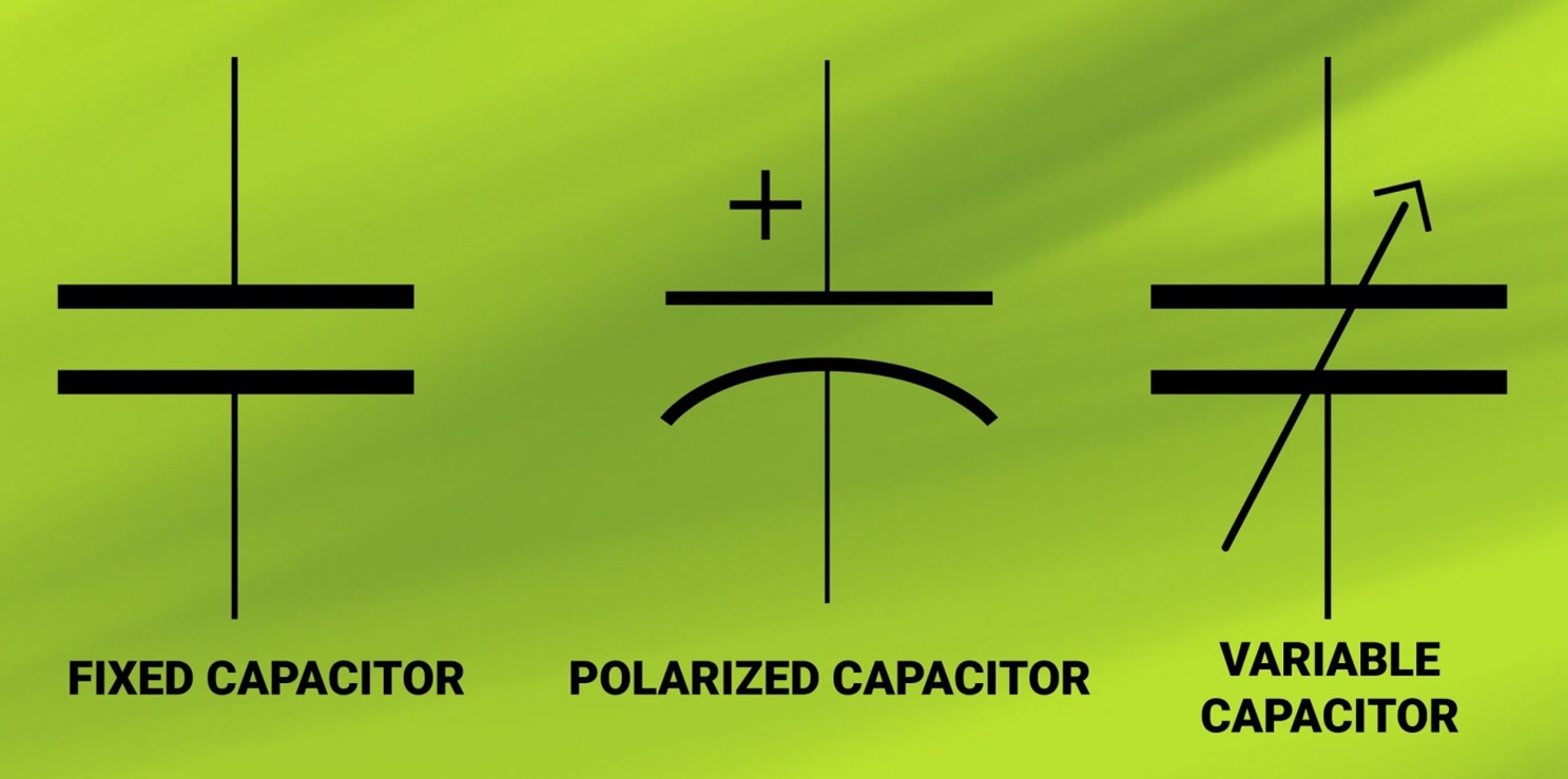
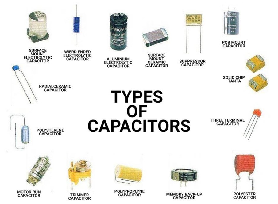
Different types of capacitors
Capacitors fall into two categories – polarized and non-polarized.
Polarized capacitors can be given positive voltage in only one direction and placed on board in only one direction. Polarized capacitors are electrolytic and tantalum capacitors
Non-polarized is the ceramic capacitor, polyester capacitor, paper capacitor which does not have polarity and can be placed in any direction.
Capacitor selection parameters
While selecting a capacitor in any circuit users need to take care of the following parameters apart from the application/usage.
- Capacitance value
- Maximum operating voltage of the capacitor.
- Tolerance
- Breakdown voltage
- Frequency range
- Equivalent series resistance (ESR)
- Size
Manufacturers: AVX, Kemet, Vishay, Samsung, Panasonic TDK, Murata, etc.
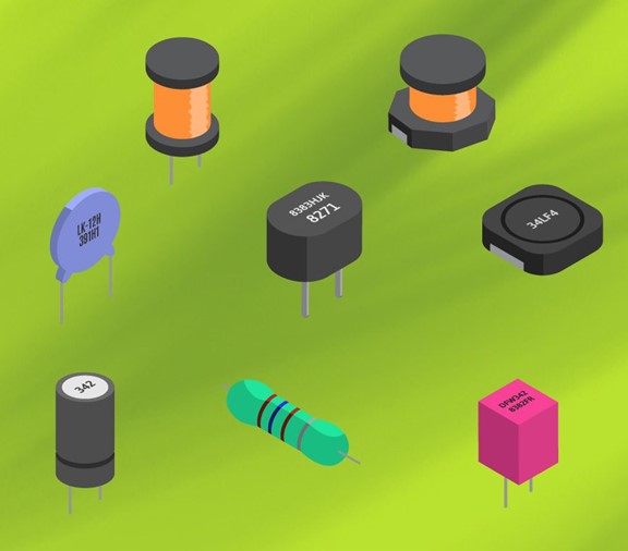
Inductors
The inductors (also called as a coil or choke) is a passive two-terminal electrical component that stores magnetic energy when an electric current is passed through it. It’s an insulated wire wound into a coil around a core of some material (air, iron, powdered iron, or ferrite material) in a spiral form.
The inductor is denoted by inductance ‘L’ and the measuring unit is Henry (H). Inductors have values that typically range from 1 µH to 2000 mH.
When the time-varying current flows through an inductor, the magnetic field is created which induces an electromotive force (e.m.f.) (voltage) in the inductor. Voltage V, across an inductor of inductance L, is given by:
V = L di/dt
That is, there is a voltage across the inductor only if the current through it is changing; DC produces no voltage through an inductor. In general, inductor blocks the AC and passes the DC.
The energy stored in an inductor with value ‘L’ Henries is given by;
E = 1/2 Li² energy E is in Joules, and I is in ampere.
An ideal inductor has zero resistance and zero capacitance. However, real inductors have a small value resistance associated with the winding of the coil and whenever current flows through it, energy is lost in the form of heat.
Application of inductors
- In buck/boost power regulators
- In filter circuits in DC power supplies
- Isolating signals
- In transformer to step up/down the AC voltage level
- In oscillator and tuning circuits
- For generating voltage surges in fluorescent lamp sets
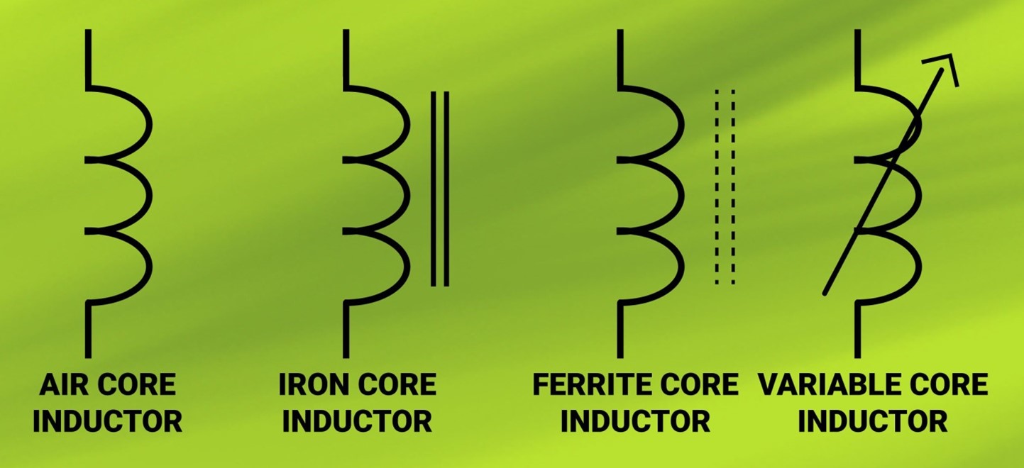
Types of inductors
Inductors are mainly classified depending on the core material used and operating frequency. The following are the different types of inductors and available in through-hole as well as SMD package based on the construction.
- Iron cored inductors
- Air cored inductors
- Powdered iron cored inductors
- Ferrite cored inductors
- Variable inductors
- Audio frequency inductors
- Radio frequency inductors
Inductor selection parameters
While selecting an inductor in any circuit user needs to take care of the following parameter apart from the application/usage.
- Inductance value
- Tolerance
- Maximum current rating
- Shielded and non-shielded
- Size
- Q ratings
- Frequency range
- The resistance of the inductor
- Type of core used
Manufacturers: Murata, TDK, Bourns Inc., Abracon Electronics, AVX corporation, Schaffner, Signal Transformer, etc.
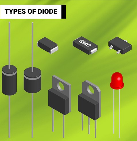
Diodes
The diode is two terminal semiconductor devices that allow an electric current to pass in one direction while blocking it in the reverse direction. The diode is made up of a semiconductor device with P-type material and N-type material. Typical material used in a diode is silicon and germanium. They conduct when a minimum forward voltage (~ 0.7V for Silicon) is applied across it and remain off during reverse bias condition.
The diode symbol is represented as below and their physical packages.
Applications of diode:
- Power conversion (AC to DC)/ rectification
- Clamping the voltage
- Zener diode as a voltage regulator
- Overvoltage protection
- ESD protection
- Demodulation of signals
Type of diodes:
- Rectifier diode
- Switching diode
- Light-emitting diode
- Zener diode
- Schottky diode
- ESD diode
- Tunnel diode
- Varicap diode
- Photodiode
- The laser diode in optical communication
Size of diode packages
Diodes are available in through-hole (DIP) and SMD versions.
E.g. DIP: DO214, SMA, TO- 220 with heatsink SMD 1206, 1210, SOD323, SOT23, TO-252, D2PAK,
Diode selection parameters
While selecting a diode in any circuit users need to take care of the following parameters apart from the application/usage.
- Forward bias voltage
- Maximum forward current
- Average forward current
- Power dissipation
- Reverse breakdown voltage/peak inverse voltage
- Max reverse current
- Operating junction temperature
- Reverse recovery time
- Size
Manufacturers: Rohm Semiconductor, Diodes Incorporated, On Semi, Vishay, etc.
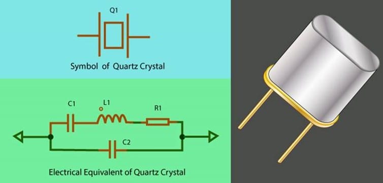
Crystals
The quartz crystal is made from a thin piece of quartz wafer. This wafer is made from silicon material. The wafer is tightly fitted and controlled between two parallel metalized surfaces which make an electrical connection. When an external voltage is applied to the plates, the crystal vibrates with a certain fundamental frequency which creates alternating waveform which swings between high and low levels. This phenomenon is known as the piezoelectric effect. Due to this property, they are used in electronic circuits along with active components to create stable clock input to the processor.
Crystal application
- Used in oscillator circuit to provide a clock input to the processor device
- Source of reference signals for RF
Crystal selection parameter
- Load capacitance
- Fundamental frequency
- Frequency tolerance
- Frequency stability
- ESR
- Operating voltage
Manufacturers: NDK, Murata, Epson, ECS, CTS, Kyocera, etc.
Relays
A relay is an electromagnetic switch that opens and closes potential-free contacts. An electromechanical relay consists of an armature, coil, spring, and contacts. When the voltage is applied to a coil, it generates a magnetic field. This attracts the armature and causes a change in the open/closed state of the circuit. It is mainly used to control a high-powered circuit using a low power signal.
There are mainly two types of relays based on constructions – electromechanical (EMR) and solid-state (SSR) relays.
A solid-state relay has a photodiode at its input side and a switching device such as transistor/FET at its output side. When a specific voltage is applied at its input, photodiode conducts and triggers the base of the transistor to cause the switching. Due to its fast switching, miniaturized form factor, low voltage requirement, and eliminating the mechanical arching, electrical noise, and contact bounce, it’s widely used in applications compared to mechanical relay.
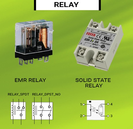
Different types of relay form
Relays are categorized based on the poles and throws such as SPDT, SPST, DPST, DPDT.
Application
- Controlling the high power circuit with isolated low power. E.g. Controlling 230V a.c. circuits with a +5V signal.
- Switching voltage ON/OFF
- Electrical MCB
- Driving diac/triac circuits
Selection parameter for relay:
- Output load type – AC/DC
- Input coil voltage for a mechanical relay
- Photodiode voltage for SSR
- Output switching voltage
- Output current
- On-State resistance
- Number of clicks/switching
- Number of poles and contacts
- Type of output contacts NC/NO
- Packages
Active devices
The basic electronic components that depend on an external power source for their operation are called active components. They can amplify signals and/or process signals. Some of the active components are transistor, integrated circuits ICs.
Transistor
The transistor is a non-linear semiconductor three-terminal device. The transistor is considered to be one of the most important devices in the field of electronics. The transistor has transformed many aspects of man’s life. There are two main functions of transistors, to amplify input signals and to acts as solid-state switches. The transistor acts as a switch when operated either in saturation or cut-off region. Whereas it amplifies signals when used in the active region. It offers very high input resistance and very low output resistance.
Transistors are categorized into bipolar junction transistor and field effect transistor based on their construction.
Type of transistor:
- BJT: NPN and PNP,
- FET: JFET, P-MOSFET,N-MOSFET
Transistor symbol is represented as below.
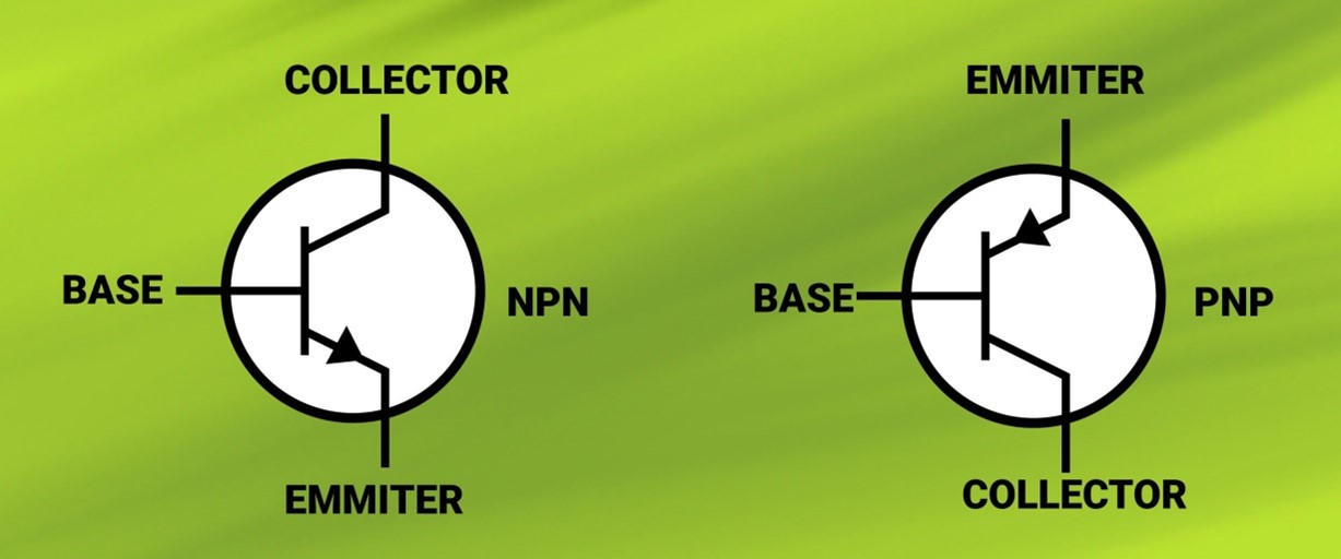
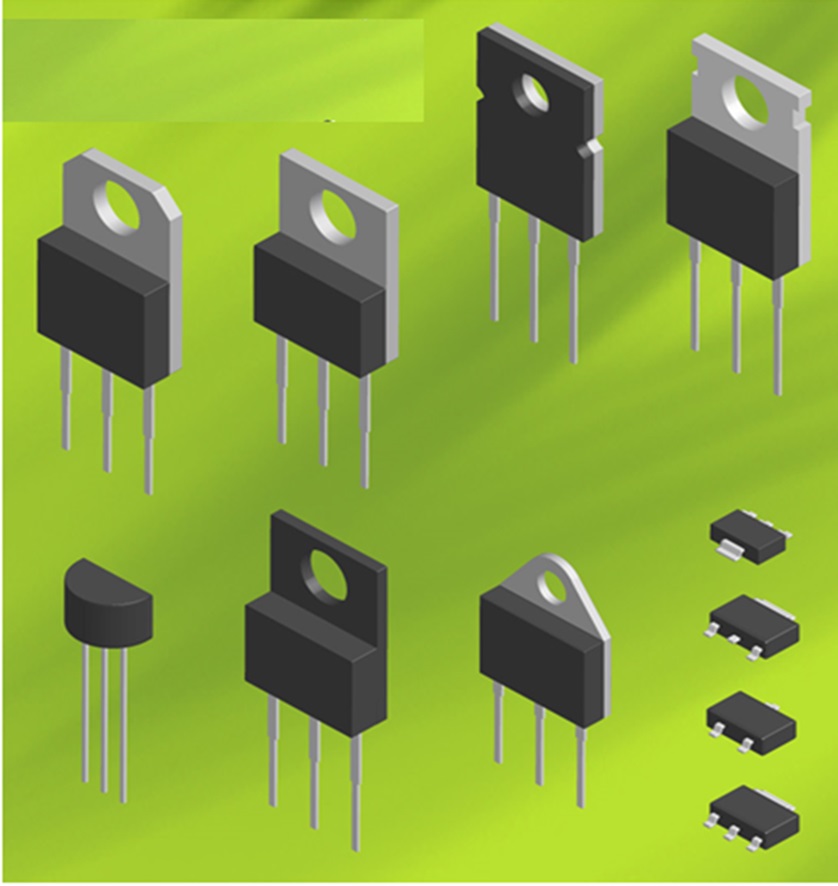
The most popular and commonly used transistors are BC547, 2N2222. Given below are a few common transistor packages:
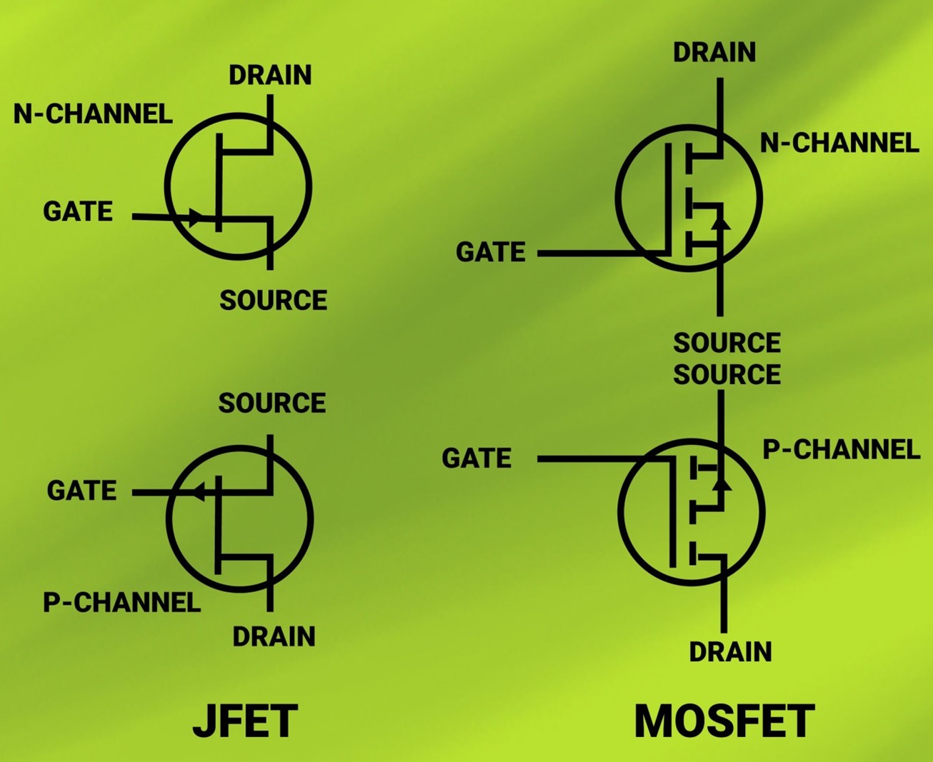
MOSFET
The MOSFET (metal oxide semiconductor field-effect transistor) transistor is a semiconductor device that is different than bipolar junction transistor in terms of construction though the applications remain the same as switching and amplifying. It has four terminals such as drain, gate, source, and body. The body is shorted with a source terminal. The gate is insulated from the channel near an extremely thin layer of metal oxide. Due to which it offers very high resistance compared to BJT.
By controlling the gate voltage (VGS +ve/-ve) width of a channel along which charge carriers flow (electrons or holes) from source to drain can be controlled. The P-Channel MOSFET has a P-Channel region between the source and drain and for N-channel MOSFET has an N-channel region.
Advantages of MOSFET over BJT:
- Very high input resistance
- Low on-state resistance
- Low power loss
- High frequency of operations
Application of transistors (BJT/FET)
- Amplification of analog signals
- Used as switching devices in SMPS, microcontrollers, etc.
- Oscillators
- Over/under voltage protection
- Modulation circuits & demodulation of signals
- Power control in invertors and chargers (high-current power transistors)
Types of transistor packages
In terms of packaging BJT and MOSFET, transistors are available in through-hole (DIP) and SMD versions. e.g. DIP: TO-92, TO- 220 and SMD: SOT23, SOT223, TO-252, D2PAK.
Transistor selection parameters
While selecting a transistor in any circuit, the user needs to take care of the following parameters:
- Maximum collector current (Ic)
- Max collector voltage (Vce)
- VBE voltage
- Saturation Vce (sat) voltage
- Current gain, hfe/ß
- Input resistance
- Output resistance
- Reverse breakdown voltage
- Max reverse current
- Power dissipation
- Operating junction temperature
- Size
- Switching time/frequency
Manufacturers: Analog Devices, Rohm Semiconductor, Diodes Incorporated, On Semi, Texas Instrument, Panasonic, Infineon, Honeywell, etc.
Integrated circuits
An integrated circuit (IC) is an electronic circuit built on a semiconductor wafer, usually made of silicon. On this wafer, there are millions of miniaturized transistors, resistors, and capacitors, which are connected by metal traces. The ICs are powered by an external power supply for their operations. ICs perform specific functions such as data processing and signal processing. The entire physical size of the IC wafer is extremely small compared to that of discrete circuits hence it is called a microchip or simply chips. Because of their small size, ICs have low power consumption.
Types of ICs
ICs are categorized as digital, analog, and mixed-signal ICs based on their circuit functionality.
Digital ICs
Digital ICs can be divided into further two categories for the sake of simplicity:
- Simple ICs: Timer, counter, register, switches, digital logic gates, adder, etc.
- Complex ICs: Microprocessor, memories, switching ICs, ethernet MAC/PHY.
A microprocessor/microcontroller is an integrated circuit, which can process the digital data. For example, temperature sensor data can be read by a microprocessor and using its internal logic to perform control functions such as switching an air-conditioner ON or OFF. The ability to program a microprocessor gives it the flexibility to be used in a wide range of applications. Some of the applications are consumer electronics (microwave, washing machine, TV), industrial applications (motor control, process control), communication applications (wireless communication, telephony, satellite communication).
A microprocessor is a complex IC having an inbuilt central processing unit (CPU) consisting of an arithmetic logic unit (ALU), registers, buffer memory, clock. The processor does not have inbuilt memory and needs to interface RAM and ROM externally. Applications: computers, laptops, servers, basically for high-end processing.
A microcontroller is an integrated circuit that has CPU, inbuilt memory, general-purpose IO’s, communication interface such as SPI, I2C, UART, ADC, DAC, PWM. Depending on the size of memory and interface microcontrollers are targeted for specific applications. Applications: Embedded devices such as washing machines, weighing scales, CNC machines, etc.
Digital signal processing (DSP) controllers are a type of processor which are used in high-computing applications such as image processing, speech processing, video compression, etc.
Analog ICs
Operational amplifiers, differential amplifiers, instrumentation amplifiers, RF devices, ADCs, DACs.
Interfacing ICs – RS232 driver, ethernet, CAN bus drivers, buffers, and level converters.
Power ICs – Voltage regulators such as linear regulators, LDOs, switching regulators
Field programmable gate array – FPGA, mixed-signal FPGA
IC packages
IC’s are available in different packages and pin counts such as DIP and SMD. Below are some of the popular and widely used packages.
| Package | Package name and pin count |
| Small outline package | SOIC-8,12,14,16, 24 TSSOP |
| Through-hole package | DIP-8,12,14,16,24, |
| Ball grid array | BGA 44, 48… 1000, etc. |
| Flat package | QFN , DFM 44 etc. |
Typical selection parameters
While selecting an IC in any circuit user need to consider about following parameters apart from the application/usage.
Digital ICs
- Operating voltage (Vcc): +2.5V, +3.3V, +1.8V, +5V, +12V/-12V
- Maximum operating frequency
- Switching time and maximum data rates
- IO voltage level (TTL5V, CMOS), max tolerance, VIH, VIL, VOH, VOL
- IO setup time, hold time, data valid time
- Type of IO: Digital or analog pin
- Open collector or totem pole output
- Total number of IOs required for application
- Type of communication interfaces such as SPI or I2C and speed
- Power dissipation.
- Commercial 0° C to 60° C, mil-grade -55° C to 125° C, industrial -40° C to 85° C
- Size
Analog ICs
- Operating voltage (Vcc): +2.5V, +3.3V, +1.8V, +5V, +12V/-12V
- Ref voltages
- Maximum and minimum output voltage
- Offset voltages and current
- CMRR, PSRR
- Input signal magnitude range
- Type of digital communication interface and speed
- Power dissipation
- Commercial 0° C to 60° C, mil-grade -55° C to 125° C, industrial -40° C to 85° C
- Size
SMT device sizes
The component sizes of the selected SMT components are important while manufacturing the electronic product. The assembler should have the capability to assemble the small size components on the PCBs. The passive components such as resistors, capacitors, and inductors which have two leads are found in standard sizes as shown in the table below. The SMT component sizes are given in inches as well as metric systems. The most common sizes are in inches such as 0402, 0603,0805 1210, etc.
The table below gives the packages of SMT two lead components and their sizes.
COMMON PASSIVE SMT PACKAGE CODE
| SMD PACKAGE TYPE IPC Standard |
DIMENSIONS | DIMENSIONS |
| MM Metric Standard |
INCHES | |
| 2920 | 7.4 x 5.1(7451) | 0.29 x 0.20 |
| 2725 | 6.9 x 6.3(6936) | 0.27 x 0.25 |
| 2512 | 6.3 x 3.2(6332) | 0.25 x 0.125 |
| 2010 | 5.0 x 2.5(5025) | 0.20 x 0.10 |
| 1825 | 4.5 x 6.4(4564) | 0.18 x 0.25 |
| 1812 | 4.5 x 3.2(4532) | 0.18 x 0.125 |
| 1806 | 4.5 x 1.5(4516) | 0.18 x 0.06 |
| 1210 | 3.2 x 2.5(3225) | 0.125 x 0.10 |
| 1206 | 3.0 x 1.5(3216) | 0.12 x 0.06 |
| 1008 | 2.5 x 2.0(2520) | 0.10 x 0.08 |
| 805 | 2.0 x 1.2(2012) | 0.08 x 0.05 |
| 603 | 1.6 x 10( (1608) | 0.06 x 0.03 |
| 402 | 1.0 x 0.5(1005) | 0.04 x 0.02 |
| 201 | 0.6 x 0.3(0603) | 0.02 x 0.01 |
Basic electronic component part numbers and datasheets
Basic electronic components are identified with their respective manufacturer part numbers (MPN). They are also identified by distributor/vendor part number (VPN).
Each basic electronic component has its datasheet which explains its performance, features, and specifications. For example, for a 100-ohm resistor:
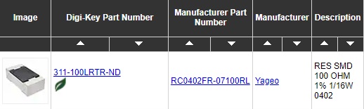
Component distributors
Electronic component distributors are a key resource for supply chain management. They are a single-window source of components from where a designer can buy components directly rather than buying from an individual manufacturer. Distributors stock components from different manufacturers and provide a simple and efficient web portal interface for selecting and purchasing components.
Most widely known component distributor in the world are as follows:
- Digi-key
- Mouser
- Arrow
- Avnet
- Future Electronics


