Contents

On-demand webinar
How Good is My Shield? An Introduction to Transfer Impedance and Shielding Effectiveness
by Karen Burnham
Component selection is one of the important steps in the PCB design process. As a designer, be aware of the common errors that occur in discrete components. This will help you in eliminating the prominent errors that arise during circuit board assembly.
Check out our PCB component sourcing and stocking services to get your electronics to market fast!
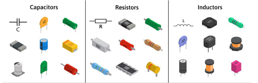
Electronic components are available individually (discrete) and in IC packages. Discrete components can be either active or passive. Resistors, capacitors, inductors, transformers, transistors, switches, diodes, and microprocessors are a few examples of discrete parts.
Before moving on to the common errors in discrete components, it is necessary to understand the source of these breakages. The following are the potential causes:
- Voltage fluctuation
- Component aging
- Excessive heat
- Corrosion
To mitigate these causes consider these guidelines:
- Procure components from reputable suppliers.
- Watch out for counterfeit parts.
- Ensure adequate component spacing.
- Incorporate board protection techniques such as conformal coating and surface finishes to avoid overcurrent and overvoltage faults.
- Consider the thermal sensitivity as per your design requirements. For instance, parts used in aerospace and defense PCBs should tolerate very low to very high temperatures.

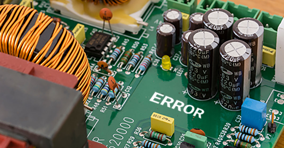
Why do failures occur in discrete components?
Errors in discrete components occur due to various electrical, thermal, mechanical, and chemical reasons. Electrical stress, which is caused by voltage breakdown and current burnout, is the most prevalent cause.
In this article, we will discuss the causes of failure associated with common electronic components like capacitors, resistors, and inductors.
What are the most frequent causes of capacitor failure?
Capacitors are one of the essential discrete components in any electronic circuit. They are used for various applications such as bypassing noise, decoupling, impedance matching, filters, etc. In this section, we will have a look at a few common factors that influence capacitor breakdown.
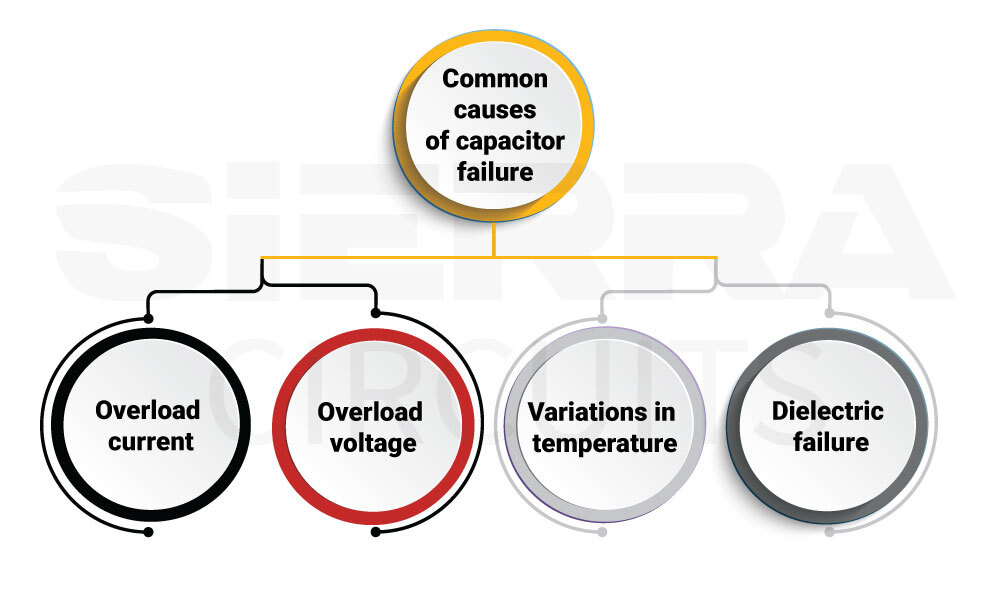
Overload current and voltage
Capacitors will heat up when exposed to high transient currents or voltages above their rated values. This will eventually cause the dielectric to break, altering the capacitance value and resulting in short-circuit.
Variations in temperature
Overheating may have a significant impact on the reliability of the capacitor. High operating temperatures, fluctuating ambient temperatures, poor insulation resistance, high power factor, and low dielectric strength are all potential causes of overheating. Low insulation resistance results in large leakage currents at high temperatures. Always choose insulation material with relatively high resistance to avoid component breakage due to thermal effects.
The dielectric strength and insulating resistance of the capacitor are mostly decreased by the presence of moisture. This results in high leakage currents. Utilize hermetically sealed capacitors as they are more dependable when compared to the standard ones.
Embedded passives improve heat dissipation, see how to design a PCB with embedded components to know more.
Dielectric failure
When a solid insulator is sandwiched between two conductors and very high voltage is applied across the conductors, the dielectric may experience an electrical breakdown. The atmosphere, the material’s quality, and high voltage gradients are the factors that affect the dielectric’s susceptibility to malfunction. The majority of dielectric materials slowly deteriorate over time, becoming brittle and more prone to fracture. The process will be accelerated for the ones that operate under a high-temperature range. Cleaning the capacitors with chemicals or water could also result in dielectric breakdown.

PCB Design for Assembly Handbook
6 Chapters - 50 Pages - 70 Minute ReadWhat's Inside:
- Recommended layout for components
- Common PCB assembly defects
- Factors that impact the cost of the PCB assembly, including:
- Component packages
- Board assembly volumes
Download Now
Signs of capacitor failure
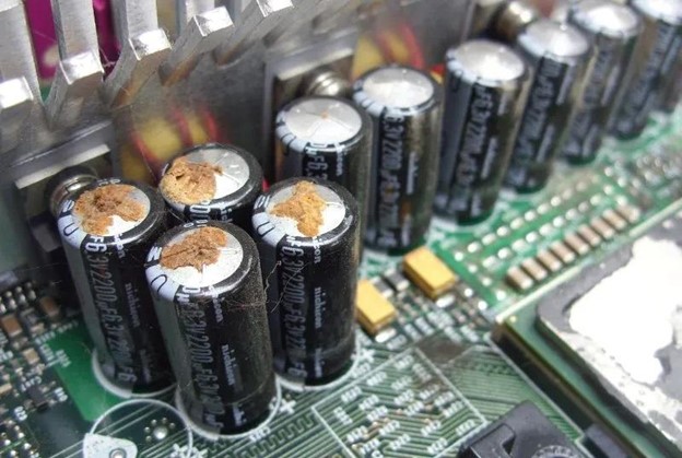
- Oil leakage raises the capacitor’s temperature and impedance.
- Excessive heat or internal fluid leaks are the usual causes of capacitor deformation.
- Scratched wires, which are brought on by over current. This can be viewed during thermal imaging.
- Burnt valve cap protrusion is an obvious symptom of stress and will likely result in a failure when it breaks.
- Rise in temperature may be a sign that the capacitor is setting out to fail.

How do you choose the right capacitor?
Consider the following criteria before you select a capacitor for your design.
- Voltage rating
- Value of capacitance
- Temperature rating
- Temperature coefficient
- Tolerance
- Humidity
- Operating cycles
- Maximum current
- Storage and packaging sizes
What are the most common causes of resistor failure?
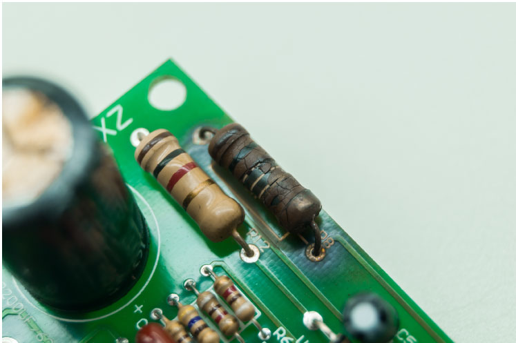
Heat dissipation during circuit operation is the usual cause of resistor malfunction. Hence, it is crucial to assess a resistor before utilizing it in your design. A resistor’s characteristics will be modified due to prolonged heat, and eventually the component will fail, causing an open circuit.
Evaluate resistor failures by considering the below-mentioned parameters:
- Impacts of shock and vibration cause the resistors to overheat.
- Prolonged usage will deteriorate the resistors and result in undesired resistance.
- Overheating results in open windings in the case of wire wound resistor.
- Resistors’ reaction to dirt build-up, insulation failure, and humidity causes a short circuit.
- Properties of the resistive material impact the resistance value of film resistors.
How do you choose the right resistor?
Resistance and tolerance are the two common criteria that influence selection.
Additionally, consider these characteristics while choosing one:
- Maximum operating temperature
- Temperature coefficient
- Life span
- Thermostability
- Power and thermal ratings
- Resistor noise
- High-frequency behavior
- Size of the resistor
- Accuracy
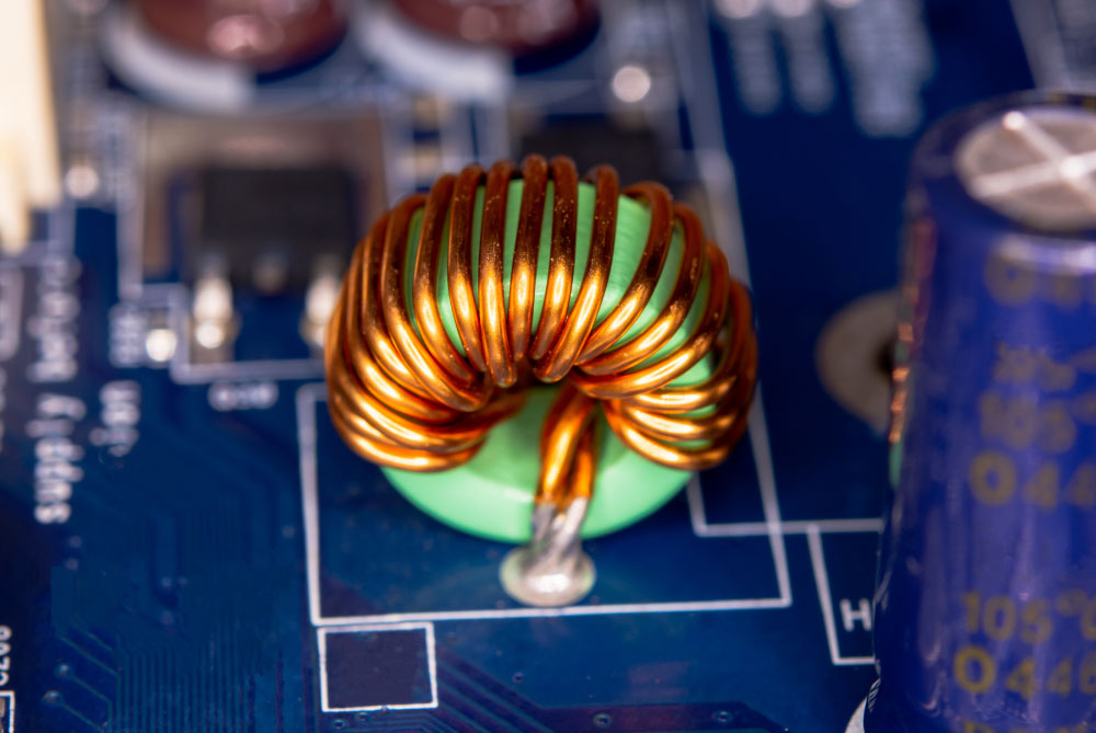
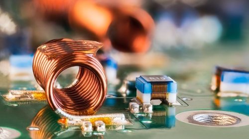
What is an inductor’s most typical failure mode?
The heat stress due to open circuit is one of the main reasons for inductor failure. An overheated inductor behaves like a shorted coil resulting in a significant current spike and melted insulation.
How to choose an ideal inductor for your design?
Consider the following parameters while choosing inductors for your design.
Inductance value
Inductance is certainly the most important aspect of any inductor. The variables that affect the inductance value are the number of turns in the coil, coil area, and core material.
The number of coil turns and its area: Inductance is directly proportional to the number of coil turns and area.
Core material: Inductance increases with increasing magnetic permeability of the core around which the coil is wound.
Coil length: Coil’s length is indirectly proportional to its inductance.
Current ratings
An inductor’s current ratings include rated current and saturation current.
Rated current refers to physical characteristics and indicates the maximum direct current that can flow through the component.
Saturation current refers to the minimum direct current required to make the magnetic field saturated.
Q factor
It is the ratio of the reactance to the effective resistance of an inductor. This value depends on the test frequency which is frequently stated in datasheets. If you’re working on high-speed designs, always choose an inductor with a high Q factor to reduce signal losses.

High-Speed PCB Design Guide
8 Chapters - 115 Pages - 150 Minute ReadWhat's Inside:
- Explanations of signal integrity issues
- Understanding transmission lines and controlled impedance
- Selection process of high-speed PCB materials
- High-speed layout guidelines
Download Now
Tolerance value
Tolerance is the difference between the actual inductance value and the value listed in the datasheet. Inductors are generally manufactured with tolerances of 5%, 10%, or 20%.
How can you tell whether an inductor is defective?
Measuring the inductor’s resistance using a multi-meter is the best way to determine whether an inductor is functional or not. A working inductor should have resistance between 1 and 10 Ohms. If the values are out of this range, the inductor is likely to malfunction.
An overview of all the common errors in discrete components has been given in this blog post. It is vital to consider all these failure modes before choosing the components for your board. In addition to this, your collaboration with your CM during the selection process will enable them to fabricate the highest quality and most reliable circuit boards. If you’d like to know more about design or manufacturing elements, let us know in the comments section.