


Contents

On-demand webinar
How Good is My Shield? An Introduction to Transfer Impedance and Shielding Effectiveness
by Karen Burnham
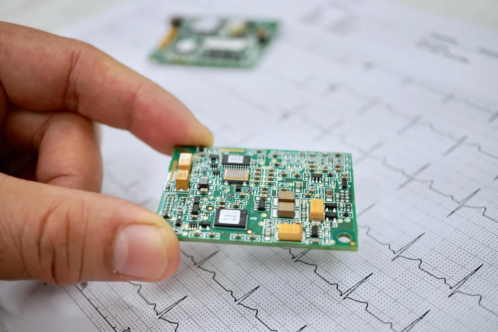
Medical science is highly reliant on electronic devices for diagnostics and treatment. Medtech PCB design for this equipment requires considerable expertise and understanding of design and regulations.
Medical technology boards must be reliable and should accommodate complex PCB layouts within smaller spaces. They also have to undergo rigorous safety and performance tests to ensure zero defects. In this article, we discuss the design considerations and standards applicable to medical boards.
4 factors to consider in medtech PCB design
Is the circuit board fire-safe? Will it operate as intended? What is the consequence if it malfunctions or is interrupted?
If these critical questions go unanswered, it can lead to undesirable results. Hence, a well-designed layout is essential to ensure accurate functionality. This includes trace width, trace space, via placements, component and dielectric material selection, etc.
1. Choosing the right technology
-
For high-performance and compact devices
As mentioned above, if you need a densely packed circuit in a smaller space, then HDI is the way to go. This technology is often used in the medical industry due to its enhanced electrical performance, lower layer count, and cost efficiency. Here, microvias are incorporated through laser drilling, which provides more space for trace routing.
Download our eBook to learn how to design an HDI PCB with signal integrity.

HDI PCB Design Guide
5 Chapters - 52 Pages - 60 Minute ReadWhat's Inside:
- Planning your stack-up and microvia structure
- Choosing the right materials
- Signal integrity and controlled impedance in HDI
- Manufacturing considerations for higher yields
Download Now
-
For wearable and lightweight devices
Flex technology is the right choice for layouts with irregular shapes and sizes. These boards can bend and fit into smaller spaces. They are also lighter, reducing the equipment’s overall weight. In addition, they are durable, reliable, and match the performance of rigid PCBs. Many prefer this technology for wearable electronic devices like fitness monitors, vital sign monitors, and hearing aids.
2. Parameters for material selection
Considering the importance of safety and reliability in medtech PCB design, the choice of material plays a critical role. The primary parameters to consider are:
- Operating temperature
- The type of laminate (Compatibility with high-speed and medium-speed signals)
- Compliance with regulations like RoHS
- Type of signal (RF signals, high-frequency signals)
- Dk and Df
- Size and shape of the board

3. Selecting components for your medical-grade circuit boards
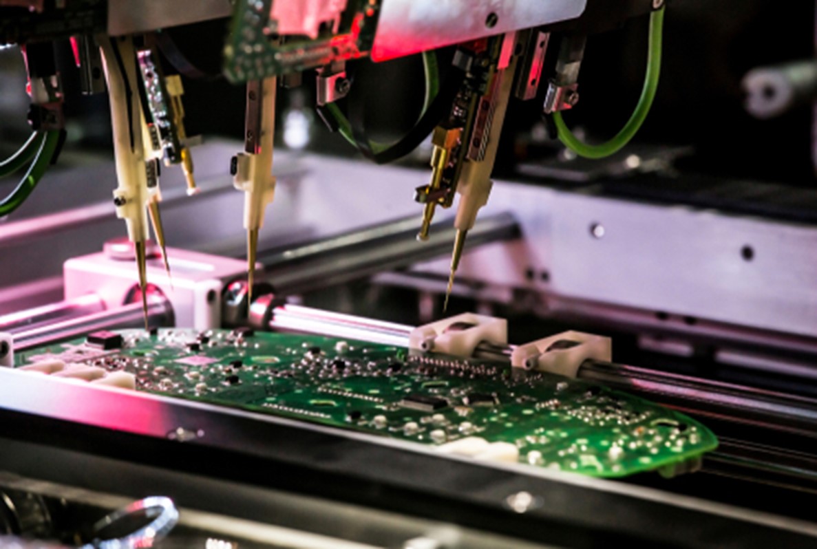
While planning the layout for medical PCBs, prefer surface mount components over through-hole parts. SMDs require less space and their size can be as small as 0.25 mm x 0.125 mm. In addition to this, drilling is not required for SMDs, which saves time and makes the circuit more cost-efficient. It also simplifies the fabrication and assembly process.
4. Facilitate testing, debugging, and modifications
Your medtech PCB design should facilitate testing and debugging. To ensure a smoother testing procedure, provide sufficient and accessible points on power lines, clock signals, and control signals. If you can keep all your pins on the outer surface of the board, it will be easier for assessment. Keep an option for modification as there is always a scope for improvement.
Medical boards manufactured at Sierra Circuits undergo multiple assessments that include:
- Automated optical inspection (AOI)
- Flying probe test
- Time-domain reflectometer (TDR)
- Solderability test
- Ionic contamination testing
- Peel test
- Microsectional analysis
Standards to build healthcare PCBs
Medical devices must adhere to strict safety and performance guidelines set by regulatory bodies. Understanding these standards and implementing these prerequisites at an early stage will be beneficial. Here, we have explained the IPC, UL, and EMI standards to help you plan your layout.
IPC standards for medical applications

The IPC standard divides circuit boards into three classes (class 1, class 2, and class 3) based on their applications. Medical equipment comes under the IPC class 3 standard. This category outlines strict guidelines for high-performance and reliable applications.
Design rules to meet IPC class 3 standards
- IPC class 3 does not allow breakout in the annular ring. The internal and external rings should not be less than 1 mil and 2 mils, respectively.
- The minimum dielectric thickness required is 3.5 mils.
- The conductor junction should not be less than 20% of the minimum trace width or 2 mils (Consider the smaller number).
- Maintain a 75% barrel fill for through-hole lead. Also, class 3 does not allow any voids in copper.
- Calculate the trace width based on the IPC-2152 standard.
IPC-2152 defines the standard for minimum trace width. Visit our blog how to optimize your PCB trace using ipc-2152 standard to know more.
Download our eBook for more guidelines on building a Class 3 PCB.

IPC Class 3 Design Guide
8 Chapters - 23 Pages - 35 Minute ReadWhat's Inside:
- IPC guidelines for manufacturing defects
- IPC standards for assembly processes
- Common differences between the classes
- IPC documents to set the level of acceptance criteria
Download Now
UL standards
Underwriter’s Laboratories (UL) is a nationally recognized testing laboratory assessing electronic devices’ safety standards. Following the UL standard means that the product has undergone rigorous tests. Hence, the manufactured product receives greater market acceptance and consumer trust.

UL standard for medical applications
To ensure user safety, UL tests for issues concerning patient care, reliability of results, product safety, information access, and data security. They evaluate the product for safety, performance, risk, and quality management. A few of the UL standards concerning healthcare products include:
- UL 1069 outlines the standard for hospital signaling and nurse call equipment.
- UL 2560 defines emergency call systems for assisted and independent living facilities.
- UL 2900 addresses the standard for software cybersecurity for network-connectable products.
- UL 1431 outlines the standard for personal hygiene and health care appliances.
Underwriter’s Laboratories also tests for other regulations and standards such as IEC/AAMI 60601-1, ISO 14971, and ISO 13485.
UL standards for PCB
As you already know, Underwriters Laboratories recognized components/materials will have to undergo one of the most stringent safety tests. Building your equipment with UL-marked components ensures quality, and getting UL certification for your medical product will be easier.
Here, the circuit panels are tested for signal integrity, interconnect stress, structural integrity, thermal reliability, conformal coating, solder mask, and conductive anodic filament test.
UL 796 is the standard for testing and safety. This depicts the guidelines for minimum thickness of base material, minimum copper thickness, spacing between the traces, withstanding voltage, etc. This is applicable to rigid and flexible panels.
Each material is assigned a comparative tracking index (CTI) based on the breakdown voltage of the insulation. For example, FR4 belongs to category 3 with a CTI between 175V to 249V.
Furthermore, you need to maintain a minimum trace width in your medtech PCB design depending on the applied voltage. The withstanding voltage between two conductors as per this standard is 40V/mil or 1.6kV/mm.
UL 94 is a flammability test. Here, the guidelines classify the materials into classes according to how they burn in different orientations.
EMI standards for medical circuit boards
Current-carrying conductors in electronic equipment can act as antennas at high frequencies. This results in EMI. Limiting EMI is essential for the uninterrupted functioning of medical devices.
FCC Title 47 rules and European CISPR have set standards for acceptable electromagnetic emissions. These standards categorize the devices into class A and class B. Comparatively, class B has to adhere to much more stringent limits.
IEC 60601-1-2 is another standard for EMI and EMC and is a part of the US Food and Drug Administration (FDA) submission requirements. This depicts the performance and safety expectations from the device in the presence of electromagnetic interference.
Ways to reduce EMI
The main reasons for EMI are improper trace routing, poor circuit design, improper grounding, and lack of shielding. By incorporating good EMC practices, you can ensure that the design complies with the standards.
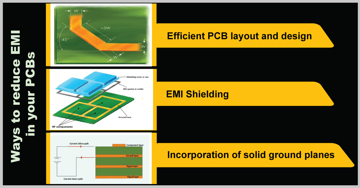
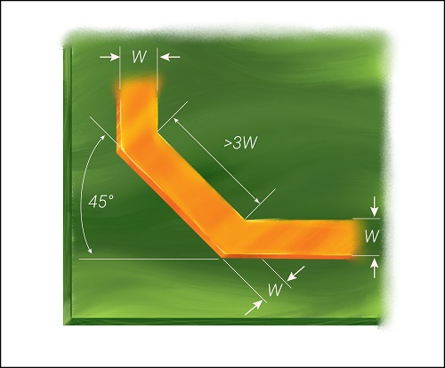
- Optimize the signal traces
Use short-length traces in your healthcare design. Do not place them close to each other, as it will lead to signal distortion and crosstalk. The current-carrying conductor can act as an antenna when there is a sharp turn. Especially, a right-angle bend increases the capacitance and changes the characteristic impedance, which results in reflections. A 45-degree bend can be incorporated as shown in the image to avoid this.
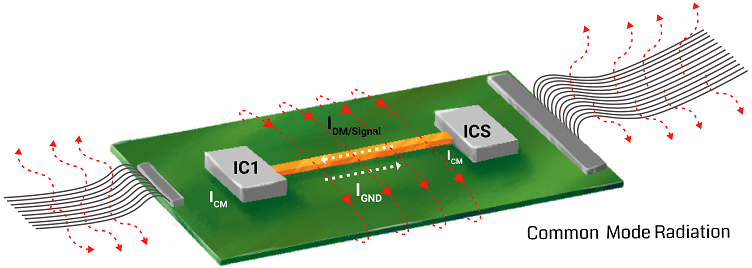
- Optimize the signal return path
Reduce the area and length of the potential return path of the signal by introducing ground planes. Additionally, avoid common-mode signal generation by adequately routing traces away from the signal return path.
- Components placement to limit EMI
Avoid placing a large number of through-hole components as they generate noise. On the contrary, you should prefer SMD as they help reduce EMI in your application.
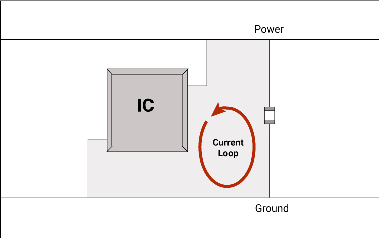
ICs can create switching noise in power rails and connected traces during operation. You can control this by placing decoupling capacitors near the IC power pin and grounding the capacitors.
- Provide proper grounding
The parasitic capacitance and inductance of the cable carrying digital and analog signals create severe EMI issues. Ground the line at both ends to avoid this.
Apart from this, vias have their own inductance and capacitance. If there is a mismatch in impedance between the via and the trace, it can cause reflection. Always place ground vias close to signal vias.
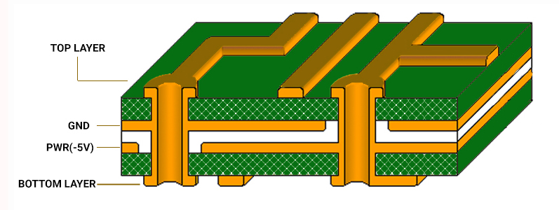
Increasing the ground area will aid in lowering the EMI by reducing the crosstalk and limiting the long signal return path. Accordingly, you can implement ground grids when providing a complete ground plane is difficult.
For more on medtech circuit board design, see 7 medical PCB design mistakes that can cause device failure.
Risk management for medical PCBs
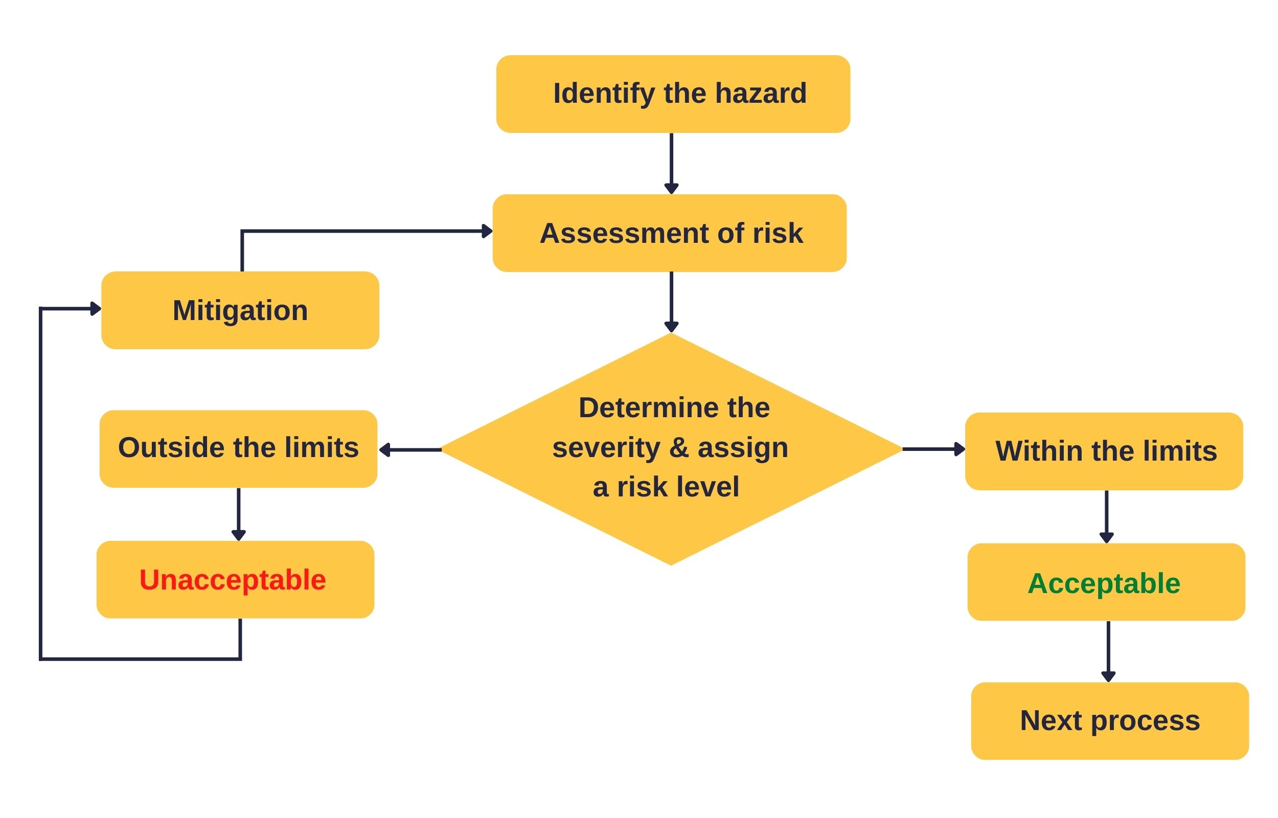
Risk management involves recognizing and preventing design failures that can become hazardous. It ensures the safety of the equipment and is now required by law.
You can evaluate the Medtech circuit for possible hazards in both standard and fault conditions. The analysis can be concerning potential flammability, toxicity, mechanical safety, and electrical safety. If you cannot eliminate the risk after identifying it, then try to reduce the impacts/consequences of failure. You can take measures to limit it to a specified level.
Many techniques exist to review the operation of a device. At the initial stage, you can conduct the hazard analysis by a what-if approach to identify potential failures.
Types of hazard analysis
Hazard and operability study (HAZOP)
A hazard and operability study is best for complex layouts with multiple process steps. This bottom-up approach is a structured examination of the layout to identify potential risks. You segregate the intricate design into ‘nodes’ and individually review them.
Failure modes and effects analysis (FMEA)
FMEA is a bottom-up and systematic approach for identifying faults and assessing their impact. Here, you review all aspects of the design to determine the possibility of failure and its effects. Record and maintain the findings in a specific FMEA spreadsheet.
Fault tree analysis (FTA)
This is a top-down approach for identifying the undesired consequence and its source. Incorporate logic gates to combine the events and analyze them. You can also use fault tree analysis to compare the various risk alternatives.
ISO 14971:2007 specifies the standards for risk management for medical equipment. This standard includes patients, operators, and other parties. The manufacturer should establish, document, and maintain a risk management process as per ISO 14971:2007.
Standards for medical equipment
While manufacturing the product, you should create a clear quality management system (QMS) to identify and remove any faults. Accordingly, the engineering teams should create rigorous test routines to verify prototypes, confirming that it match the design and safety requirements. Rules and regulations are set to ensure that only safe and reliable medical electronics reach consumers. Below, we have mentioned a few of the standards set by prominent regulatory bodies.
- FDA CFR Section 807 regulates companies regarding production, packaging, and labeling.
- ISO 14971:2007 outlines the standards to detect any hazards in equipment.
- ISO 13485 summarizes the quality management system (QMS) requirements.
- IEC 60601-1 addresses safety and performance aspects.
- IEC 61010-1 addresses the standard safety guidelines for electrical components.
- FCC rules and regulations, Title 47, define the standards for wireless applications.
As a designer, you need to pay attention to the safety and performance aspects of your medical board. A good understanding of the IPC, IES, FDA, UL, IEC, and ISO standards is essential to designing a flawless PCB. Considering these major design aspects in the early stages can make your project efficient and pass all the regulations without a hitch.
Sierra Circuits is certified by ISO, IPC, UL, and many other regulatory bodies. Our capabilities include manufacturing, assembling, and testing medtech boards for many advanced applications. If you require any assistance with your design, let us know in the comments section. We will be happy to help you out.
You can book a meeting with our experts or call us at +1 (800) 763-7503.

About Sushmitha V : Sushmitha V has a master's degree in power electronics and has over four years of experience in the PCB industry. Her areas of interest include circuit board manufacturing, assembly, IPC standards, and DFM/DFA practices.


Start the discussion at sierraconnect.protoexpress.com