


Contents

On-demand webinar
How Good is My Shield? An Introduction to Transfer Impedance and Shielding Effectiveness
by Karen Burnham
The PCB waste generated decades ago will harm our environment in the years to come. These discarded materials consist of hazardous substances such as lead, mercury, cadmium, and several other chemicals, that adversely affect life on Earth. There is a need for environmentally responsible manufacturing for RoHS-compliant PCBs across the entire consumer electronics sector in today’s scenario.
RoHS (Restriction of Hazardous Substances) restricts the use of hazardous materials, particularly found in electrical and electronic components.
This directive was instigated by the European Union in 2002. As per the initial of Directive 2002/95/EC, the six hazardous substances were prohibited for their use in electrical and electronic products. So far, there have been two upgrades to the RoHS directive, including RoHS 2 and RoHS 3. The RoHS 2 or Directive 2011/65/EU was published in 2011, while the Directive (EU) 2015/863 was published in 2015. Under Directive (EU) 2015/863 four different elements were added to the previous list of restricted elements.
What does RoHS compliant mean?
On 27th January 2003, the European Union parliament passed two legislations that impacted the electronic industry. The first one was Waste Electrical & Electronic Equipment, commonly (WEEE) it is making manufacturers responsible for the end-of-life disposal of their finished goods. The second one is more important which is the Restriction of Hazardous Substances (RoHS).
The RoHS directive makes it illegal to manufacture any electrical or electronic equipment that contains restricted materials, materials that are harmful to the environment. The legislation took full effect on July 1, 2006. The directive focuses on the smallest homogeneous part or material that can be separated from the mass of a component or assembly. Specifically, the electrical and electronic equipment entering the EU market cannot contain lead, mercury, cadmium, hexavalent chromium, polybrominated biphenyls (PBB) or polybrominated diphenyl ethers (PBDE), specifically Penta PBDE and Octa PBDE.
Impact of RoHS-compliant PCB
As of July 1, 2006, new electrical and electronic equipment entering the EU market cannot contain lead, mercury, cadmium, hexavalent chromium, polybrominated biphenyls (PBB), or polybrominated diphenyl ethers (PBDE), specifically Penta PBDE and Octa PBDE.
Other impacts of RoHS directives are mentioned below:
Lead-free manufacturing
Although the flame retardant used in laminates is not restricted, the lead-free initiative affects the supply chain. That means the PCB manufacturer cannot use a surface finish and lead solder cannot be used for assembly. In that case, lead-free soldering requires a higher temperature to solder, the raw PCB must withstand this higher temperature. New laminates require better thermal-mechanical properties to withstand lead-free manufacturing, both in terms of infant mortality and long-term stability.
Material restriction as per RoHS directives
Restriction of Hazardous Substances (RoHS) 3 directive prohibits the use of 10 hazardous elements in electronic and electrical products. Additionally, the substances and chemicals used during PCB manufacturing and PCB assembly should not contain these ten elements in the form of impurities. The permissible quantity in the form of impurity is determined in RoHS directives. For instance, the permissible quantity of cadmium is restricted to 100 parts per million (0.01%) in the form of impurity. These directives are specifically directed towards Lead and poly-brominates, and sometimes they are referred to as the lead-free directive.
EU RoHS directive has specified maximum levels for the 10 hazardous substances as shown in the table below. The last four compounds were introduced under RoHS 3 and came into effect on July 22, 2019.
| SI.NO | Restriction of Hazardous Substances (RoHS) List | Permissible Value in terms of PPM (parts per million) |
|---|---|---|
| 1. | Lead (Pb) | <1000 PPM |
| 2. | Mercury (Hg) | <1000 PPM |
| 3. | Cadmium (Cd) | <1000 PPM |
| 4. | Hexavalent chromium (Cr6+) | <1000 PPM |
| 5. | Polybrominated-biphenyls (PBB) | <1000 PPM |
| 6. | Polybrominated-diphenyl ether (PBDE) | <1000 PPM |
| 7. | Bis(2-ethylhexyl)-phthalate (DEHP) | <1000 PPM |
| 8. | Butyl benzyl phthalate (BBP) | <1000 PPM |
| 9. | Dibutyl phthalate (DBP) | <1000 PPM |
| 10. | Di-isobutyl phthalate (DIBP) | <1000 PPM |
Cost of implementation
Cost is not an issue if we are considering environmental protection and the future of living beings. But we have to understand the commerce of implementing RoHS. Every lead-free solder costs at least 20% more than lead soldering. Not only the material cost, but the energy cost also rises, Lead-free soldering needs higher reflow soldering temperatures. There is a significant cost in training personnel to deal with the change to a Pb-free environment.
Some of the lead-free materials include costs of patent licensing, whether by the end-user or solder manufacturer. Also, refining lead-free materials such as indium (In), gallium (Ga), and silver (Ag). and bismuth (Bi) is high.
Reliability concerns
Change of materials and solder to accommodate the removal of Pb requires reliability testing. Reliability testing techniques, criteria, and models would have to be refined to match the material properties of Pb-free assemblies. Some of the other concerns are listed below:
Higher-temperature soldering
Increased soldering temperature will reduce the life of components, thermal fatigue, plastic IC popcorn effect, delamination of multi-layer PCBs, etc.
Solder joint reliability
Lead-free joint reliability is less than lead soldering. Many researchers have found the long-term joint reliability of the solder is less than tin/lead solder paste.
Tin whiskers
A whisker can cause a short PCB, and this is a very serious problem, as many component manufacturers use the pure tin as their chosen lead finish to minimize costs.
The standard for RoHS (IPC-A-610)
IPC-A-610, Acceptability of electronic assemblies. The standard is provided with industry-developed and approved programs like training, certification, and instructional material. A company that provides RoHS-compliant PCB must have an IPC-trained workman to give proper attention to the changes and renewed inspection criteria.
Solder flux
Some of the solder flux used for lead or tin cannot withstand higher temperatures. In that case, if we are using the same flux used for the lead then it will evaporate, decompose, or oxide before fluxing can take place. Thus the flux for lead-free solder should be designed to withstand higher temperatures.
Factors that affect RoHS material selection
Even while selecting a base material that accepts RoHS directives, manufacturers must ensure the long-term reliability of the PCB. The reliability of lead-free PCB is no doubt lesser than the PCB which uses lead at higher temperatures. The following are the key properties considered while selecting the base material.
Decomposition temperature, Td
Typically Td is the temperature at which 5% percent of the original mass is lost to decomposition. 5% mass is a considerable amount of mass, even if the Td value is high, the peak temperatures in lead-free assembly can reach onset points of decomposition. Thus the 5 % Td value does not guarantee performance. Conversely, a low Td by the 5 percent definition is not necessarily bad if the onset temperature of decomposition is high enough.
Glass transition temperature, Tg
Glass transition temperature, Tg is the point at which the thermodynamics of a polymer from a rigid, glassy state to a softened and more deformable state. Several properties change as the Tg is exceeded, including the rate at which a material expands versus temperature.
The CTE versus expansion graph is shown above. With a higher decomposition temperature, this mid-Tg FR-4 material is much more compliant with lead-free assembly than with traditional material.
Coefficients of Thermal Expansion, CTEs
Resin system CTE values above Tg are much higher than those below Tg. Z-axis expansion induces stress on plated vias. The higher lead-free assembly temperatures result in more overall expansion for a given material. Several advanced, lead-free materials incorporate CTE values-reducing inorganic fillers. X and y-axis CTEs are also important for reliability at component and layer interfaces.
Moisture absorption
The vapor pressure of water is much higher at lead-free assembly temperatures. Absorbed moisture can volatilize during thermal cycling and cause voiding or delamination. PWBs that initially pass lead-free assembly testing may exhibit defects after storage in an uncontrolled environment as a result of moisture absorption. This should be considered when evaluating materials and PWB designs.
Time to delamination
This property is related to decomposition temperature and adhesion between material components. Thermal expansion and moisture absorption can also influence results. In multilayer PWBs, the treatment of the internal copper surfaces is also critical, among other factors.

RoHS directives for flame retardants
Flame retardants are used to reduce the concentration of heat, and the evolution of toxic gas, and delay or eliminate flashovers. RoHS and WEEE detectives also affect the flame retardants used in the resin system. The use of specific types of brominated flame retardants is prohibited by the RoHS directive. The restricted class of compounds consists of polybrominated biphenyls (PBBs) and polybrominated biphenyl oxides (PBBOs), also called polybrominated diphenyl ethers (PBDEs).
Flame retardancy is commonly achieved by bromination of the epoxy resin with tetrabromobisphenol A (TBBPA) which contains bromine within the chemical backbone. The TBBPA is reacted into the epoxy resin itself, bromine is released under excessive exposure to heat and retard burning. The RoHS directive does not restrict the use of TBBPA but it is not allowed to be released into the environment. But the WEEE directives require a separation or special handling. Halogen-free PCB materials avoid brominated flame retardants entirely, making them a safer choice for both the environment and human health.
Why Tetrabromobisphenol A (TBBPA)?
- TBBPA reacts to the resin
- The use of TBBPA is not banned in any country
- Cost-effective
- Effective in low-addition level
Component solderability
The majority of components require the use of some type of plating, somewhat close to what is used for PCBs, to provide solderability and shelf life. There are various plating methods, both from the metallurgy used to the methods of application used. Due to the speed of plating and the number of components plated every hour, as well as the different plating techniques and alloys, process control for component plating may be claimed to be more important than for PCBs.
Before the RoHS directive, the component surface finish in the majority was tin-lead. The conversion to Pb-free has resulted in the dominance of 100 percent Sn as the solderable surface finish.
It is not simple to switch from a tin lead-plated part to a lead-free finish. It may seem relatively simple to move from tin-lead to 100 percent tin, but a 100 percent tin deposit is more vulnerable to line issues such as pH control rinsing. Its effect on the surface finish is also greater than tin-lead has ever been. Similarly, converting from base metal to an exotic such as nickel palladium gold would entail the procurement of certain pricey specialized measuring instruments.
RoHS compliance flex circuits
When it comes to flexible circuit materials there are two main concerns of material selection, flame retardant molecules with bromine in adhesive resins, and heat resistance for high-temperature processing with lead-free soldering. Flexible applications need adhesive-based copper laminates, manufacturers are developing non-bromine-based flame-retardant reagents.
Without bromine molecules, new photoimageable coverlay materials have been created. Not many choices provide balanced efficiency, particularly high flexibility for dynamic flexion. Polyimide-based photo imagery coatings are the option to fulfill all practical specifications, but these polyimide products are remarkably more costly.
Why are RoHS-compliant PCBs required?
Major concern begins with the piles of electronic waste found in open junk yards across the globe. Electronic waste mostly consists of hazardous substances such as heavy metals and other chemical materials with absolutely no chemical control. The problem persists further as the acidic rainwater dissolves Lead and other harmful substances. This contaminated rainwater will be added to the water bodies. Thus, severely causing harm to aquatic life and human well-being.
Heavy metals like Lead and Mercury have an adverse effect on the human body organ and can disturb the entire central nervous system. These metals also affect the functioning of kidneys and the reproductive system. A higher intake of lead through contaminated water will reduce the reaction time of body organs such as fingers, wrists, and ankles.
RoHS initiatives will provide necessary relief for all of us. Compliance with RoHS directives by PCB manufacturers will support our fight against climate change and global warming.
How to check materials for RoHS directives?
The RoHS directives specify that the manufacturer has to provide a certificate of compliance, but not specifically which method should be used. The X-Ray fluorescence measurement instruments are efficient to check the materials. The instrument provides material analysis as well as coating thickness, two important tests in regard to WEEE/RoHS regulations. It is a non-destructive, fast, and simple way to estimate elemental concentrations in materials. Analysis of the reaction signal from products penetrated by an X-ray beam.
RoHS-compliant circuit boards
There is a steady rise in the number of electronic products ending their life in the open junkyard. These products are further sent for the trash reclamation process, which is polluting our landfills. RoHS-compliant PCBs do not contain hazardous chemicals and substances. Lead-free or RoHS-compliant PCBs are increasingly in demand due to the growing preference for environment-friendly circuit boards.
There is a steady rise in the number of RoHS-compliant PCBs manufacturers who are adhering to RoHS compliance requirements due to customer demands and stringent government policies. We are witnessing a radical shift in environmentally responsible manufacturing across the globe. Additionally, RoHS-compliant manufacturing will reduce the possible ill effects on workers during manufacturing processes.
Availability of plating finishes that are RoHS compatible, including lead-free immersion white tin, Immersion silver, OSP, electroless-nickel immersion gold (ENIG), soft bondable gold, and full-body gold finishes, will keep PCB manufacturers away from leaded surface finishes. Other compatible surface finishes include:
- ENIG (Electroless Nickel-Immersion Gold)
- IS (Immersion Silver)
- IT (Immersion Tin)
- OSP (Organic Solderability Preservative)
To know more about the black pad, and the defect seen in ENIG, read how to work around black pad in ENIG finish.
Before using lead-free finishes, RoHS-compliant PCB manufacturers must perform internal changes in RoHS-compliant PCBs design, material selection, and component assembly. Other factors, the PCB manufacturer needs to pay more attention are the shelf life of the final product, working conditions, and storage.
As more and more customers are started to demand lead-free products, assuming all requirements are fully met, we will likely witness the prevalence of green manufacturing worldwide.
Status of PCB manufacturing processes in regard to the RoHS initiative
PCB manufacturers are bound by RoHS directives for using lead-free substrate materials, inks, solder masks, surface finishes, and other chemicals during the manufacturing processes. Additionally, PCB manufacturers and assembly service providers must ensure the discrete components, solder joints, and heat sinks are RoHS compliant.
Out of the 10 restricted materials, the replacement of lead is causing inconvenience to the PCB manufacturers. Higher processing temperatures associated with lead-free alloys are a major concern among PCB manufacturers.
To understand their concern, let’s have a look at the status of the different manufacturing processes that require RoHS-compliant testing.
- Preparation of laminates: There are several limitations of the lead-free FR4 material during the assembly processes. However, the availability of advanced materials, such as Isola IS410, Isola FR415, and Polyclad 370HR that can withstand higher temperatures and can ensure standard electrical performance, is ideal for PCB manufacturing processes. A few important characteristics of lead-free materials that are used for the preparation of laminates and prepreg include Td, T-260 & T-288, and CTE (Coefficient of Thermal Expansion). The Tg ratings are also useful while deciding the selection of material based on the type of application.
- These manufacturing processes are carried out at higher temperatures than that of leaded processes. RoHS-compliant materials must be capable of handling higher reflow temperatures during assembly processes. However, the choice of RoHS material is still dependent on the type of application. The lead-free materials must assure standard electrical performance with low losses.
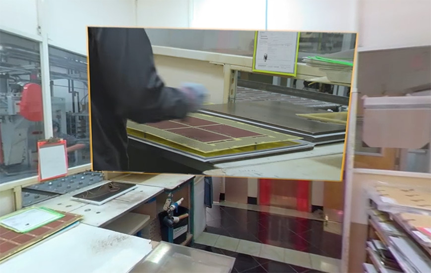
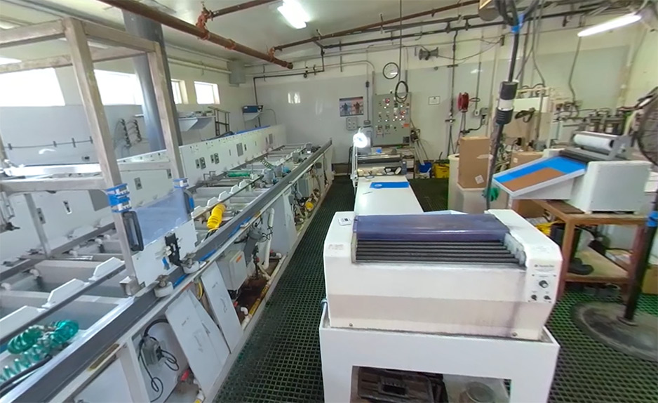
-
Sierra circuit’s solder mask lab facility - Application of solder mask and legend inks: The solder mask and legend inks must be free of hazardous material and withstand higher temperatures. Typically, there is a higher possibility of noticeable discoloration at higher temperatures.
- Availability of RoHS-compliant surface finishes: Availability of several surface finishes such as plated nickel gold, electroless nickel immersion gold, immersion silver, and palladium will dissolve the need for leaded surface finishes.
- Application of stencil: Applying the stencil to the lead-free circuit board is the first step of the assembly process. The lead-free solder alloy such as SAC305 is increasingly used for surface-mount technology, wave soldering, and wire soldering.
Difference between WEEE, REACH, and RoHS
To protect our environment and the future of human beings, During the 2006-2007 period the European Union parliament passed some legislation. It was the most comprehensive of current global assessment programs for human health and environmental characteristics. The legislations were, REACH regulation, RoHS, and WEEE directives as a strong action to protect our nature.
The REACH Regulation (Regulation EC No 1907/2006) came to effect on June 1, 2007. It is the central act of the new European chemicals policy. At this time, Council Regulation (EEC) 793/93 on Existing Substances (EU Risk Assessment Regulation) was revoked and replaced by REACH, establishing the European Chemicals Agency. REACH regulated the entry of various chemicals or equipment that use those chemicals from entering EU countries. All manufacturers and importers of chemicals must identify and manage risks linked to the substances they manufacture and market.
Restriction Of the use of certain Hazardous Substances in Electrical and Electronic Equipment (RoHS). It states that member states shall ensure that new Electrical and Electronic Equipment (EEE) put on the market shall not contain Pb, Hg, Cd, Cr (VI), polybrominated biphenyls (PBBs), and polybrominated diphenyl ethers (PBDEs) above-permitted levels. All other flame retardants are compliant with the provisions of the RoHS Directive and can hence be used in EEE.
The EU legislation promoting the collection and recycling of Waste of Electrical and Electronic Equipment (WEEE Directive) has been in force since February 2003 (EU Directive 2002/96/EC). This directive calls for the selective treatment of plastics containing brominated flame retardants. Also, PCBs used in cell phones with surface areas greater than 10 cm2 are required to be removed. Regardless of what flame retardant is used.
Our Capability
PCB fabrication:

Sierra Circuits has delivered lead-free or RoHS-compliant PCBs for the last decade. Our laminates can withstand higher temperatures and give out consistent performance over a period of time. We may be bound by the laws of manufacturing, but we adhere to the laws of nature as well. Join us as we take a pledge to keep our planet green.
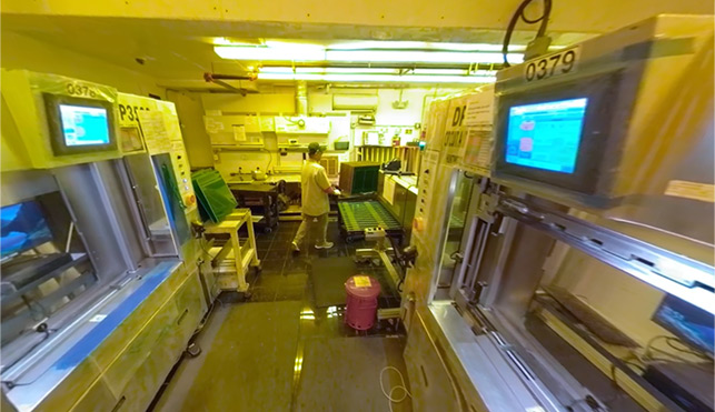
PCB assembly:
Sierra Circuits is Fully Equipped & delivering lead-free or RoHS-compliant PCB Assemblies for various customers for more than a decade..
We have a World class manufacturing setup in the USA with all sophisticated High Speed latest technology SMT machines that are capable of manufacturing Lead-free / RoHS PCB assemblies. Our machines can handle the smallest components 01005. and BGA’s with 0.3 mm pitch, etc.
We have designed our manufacturing setup to handle all kinds of electronics PCB assemblies including flex / rigid PCBA. SMT lines are capable of handling Hi-Mix & low volume PCBA, which is mainly the requirement of all types of prototype assemblies. We have Juki & Europlacer SMT machines with facilities for reflow soldering, wave soldering, selecting soldering, X-Ray inspection, AOI, SPI, ICT, FPT, BGA rework, etc.

Design for Manufacturing Handbook
11 Chapters - 96 Pages - 90 Minute ReadWhat's Inside:
- Annular rings: avoid drill breakouts
- Vias: optimize your design
- Trace width and space: follow the best practices
- Solder mask and silkscreen: get the must-knows
Download Now


