


Contents

On-demand webinar
How Good is My Shield? An Introduction to Transfer Impedance and Shielding Effectiveness
by Karen Burnham
IPC flex PCB testing standards, such as IPC-2223 and IPC-9204, define how manufacturers should evaluate the electrical and mechanical reliability of FPCs (flexible printed circuits). These benchmarks provide a testing framework to assess flex boards under conditions like bending and high-voltage exposure.
Being a PCB designer, understanding these testing protocols is essential for creating manufacturable designs that comply with IPC requirements.
In this article, you’ll learn the key IPC testing benchmarks that fabricators should follow to ensure the quality and reliability of flex and rigid-flex printed circuits.
Highlights:
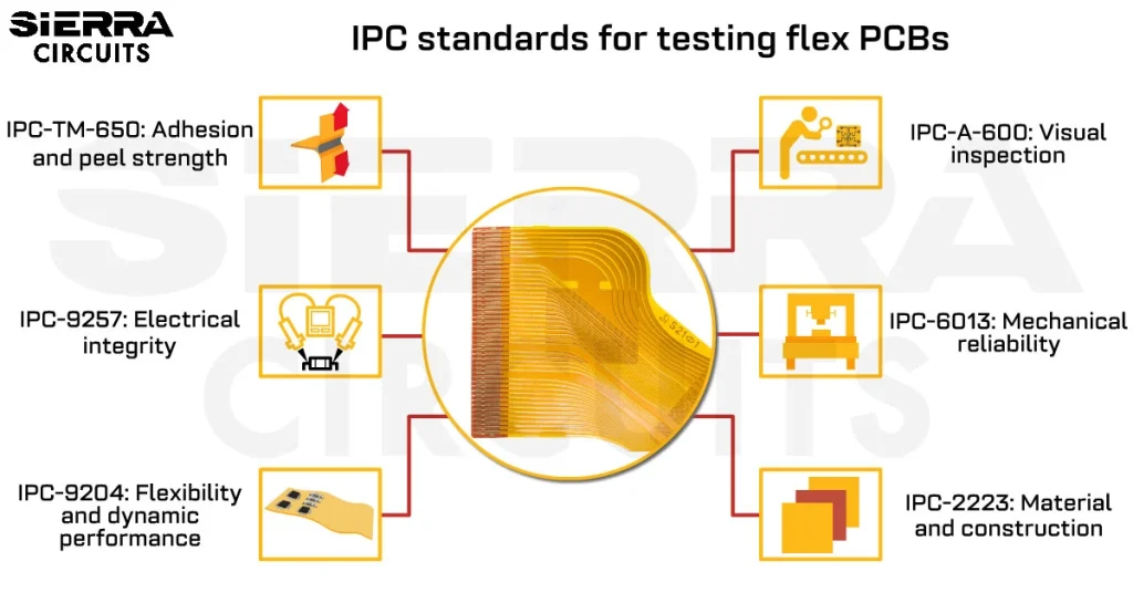
IPC flexible PCB testing standards include:
- IPC-A-600: Sets visual inspection criteria to catch defects like cracks or delamination, ensuring flawless flex boards.
- IPC-TM-650: Provides methods like peel strength (2.4.9) and HiPot (2.5.7.2) testing to confirm adhesive and dielectric reliability.
- IPC-TM-650 2.6.7: Assesses thermal shock resistance, ensuring flex boards handle rapid temperature changes.
- IPC-TM-650 2.5.5.7: Uses TDR impedance testing to maintain signal quality in high-frequency flex PCBs.
What are the IPC standards for testing flex PCBs?
| IPC standard | Scope | Use cases |
|---|---|---|
| IPC-6013 | Qualification and performance specifications. | Implemented during prototyping to validate thermal cycling and bending performance early in development. |
| IPC-2223 | Component mounting and various interconnection systems. | Apply when designing hybrid systems (e.g., RGB display interfaces, wearables, IoT devices) to ensure seamless integration. |
| IPC-9204 | Flexibility and stretchability. | Suitable for foldable smartphones, wearable health monitors, or other flexible electronics to confirm mechanical resilience. |
| IPC-9257 | Electrical testing procedures. | Verifies electrical performance before final production and deployment. |
| IPC-TM-650 | Compilation of standardized test methods for electronic materials and processes. | Ensures testing consistency and reliability across production lines. |
| IPC-TM-650 2.6.21B | Test method for evaluating the service temperature of metal-clad flexible laminates, cover materials, and adhesive bonding films. | Assesses thermal reliability and guides material selection for heat-intensive applications. |
Download our eBook to learn how to design a reliable flex PCB.

Flex PCB Design Guide
10 Chapters - 39 Pages - 45 Minute ReadWhat's Inside:
- Calculating the bend radius
- Annular ring and via specifications
- Build your flex stack-up
- Controlled impedance for flex
- The fab and drawing requirements
Download Now
7 IPC-compliant flex PCB testing methods
Contract manufacturers conduct these tests to ensure high-quality FPCs:
1. Visual inspection to detect physical defects
It involves a thorough examination of the printed board for any defects, such as delamination, cracks, or foreign objects. This type of inspection uses both manual and automated methods to identify issues early in the process. FPCs must meet the criteria outlined in the IPC-A-600 document, which defines acceptability criteria for visual quality.
1.1 Manual visual inspection
- Involves examining the board with the naked eye or using magnification tools like microscopes or magnifying glasses.
- The board is compared with design documents to confirm that the board meets all specifications.
- Common issues to look for include scratches, cracks, oxidation, delamination, contamination, component misalignment, solder defects (e.g., insufficient solder, solder bridges), and incorrect labeling.
1.2 Automated optical inspection (AOI)
- It is a non-contact testing method that uses high-resolution cameras and advanced software to detect a wide range of defects.
 process")
- It identifies issues like insufficient solder, bridging, missing or misaligned components, delamination, and foreign particles.
- Automated optical inspection can detect lead-level faults on components with a pitch as small as 16 mil, making it ideal for high-volume production where consistency and accuracy are critical.
1.3 Automated X-ray inspection (AXI)
- AXI provides a non-destructive view of hidden defects. within the circuit boards.

- It’s used to inspect concealed solder joints beneath surface-mount components and verify through-hole connections.
- AXI reveals internal flaws like voids in solder joints, wire bond issues, and structural defects in multilayer boards.
1.4 Automatic laser test (ALT)
- ALT is a part of IPC rigid-flex PCB testing standards. It is a non-contact laser-based method used to measure critical PCB dimensions with high precision.
- Laser beams are projected onto the board surface, and reflections are analyzed to map the 3D profile.
- This data is compared against the design files to detect dimensional deviations.
- ALT is useful in the pre-reflow phase to check solder paste volume, alignment, and surface irregularities.
- It’s highly recommended for rigid-flex assemblies.
14-point visual inspection checklist for FPCs
Sierra Circuits follows these inspection methods that comply with IPC flexible circuit standards.
You can use this checklist to perform a thorough quality check when reviewing boards received from your fabricator.
- Verify if the FPC dimensions align with design specs to ensure proper fit.
- Check if hole sizes and pitch match the design for component placement.
- Inspect component placement to confirm adherence to design requirements.
- Look for scratches, deformations, oxidation, and rough edges.
- Confirm that the FPC’s solder pads and pins are perfect, present, and free from soldering defects like voids or bridges.
- Evaluate pad plating for stiffness, roughness, and signs of bulging.
- Inspect the coating and check for uniform plating flux distribution, sufficient hardness, precise placement, and color.
- Examine the substrate and cover layer for creases, wrinkles, or foreign objects.
- Measure pad and overlay sizes. The standard tolerances are ±0.3 mm (for <100 mm) or within 0.3% (for >100 mm)
- Limit adhesive or coating spread to a maximum of 0.2 mm. Ensure that the combined variation from the cover layer, punch, and adhesive/coating around connection points is at least 0.05mm.
- Validate part numbers and markings are legible and comply with silkscreen specs.
- Inspect connectors for bent pins or misalignment.
- Check conductive traces for any breaks, neck-downs, or inconsistencies.
- Detect micro-cracks or any defects during flexing.

2. Electrical testing to validate circuit integrity
This test confirms that bare flex PCB traces match its intended netlist. It checks for open (continuity test) and short (isolation test) circuits.
2.1 Continuity test
This test ensures all intended electrical connections are intact, without breaks or open circuits. It checks for broken traces, incomplete etching, or poor plating.
We follow these steps for a continuity test:
- Mount the PCB in the test fixture or system.
- Load the netlist or Gerber data to define expected connectivity.
- Apply a low voltage across each net and measure resistance.
- Identify the opens caused by physical damage or fabrication issues.
- Generate a pass/fail report for traceability and quality control.
2.2 Isolation test
It verifies that there are no unintended electrical connections (short circuits) between different conductive layers, traces, or components within the circuit.
We follow these steps to perform an isolation test:
- Apply high voltage (typically 250–500 VDC) between isolated nets or conductors.
- Monitor the leakage current to assess insulation performance.
- Calculate insulation resistance and compare it to IPC-TM-650 standards.
- Detect low-resistance paths or unintentional shorts between nets.
- Ensure dielectric materials can withstand operating voltages without failure.
- Log all test results to ensure compliance and traceability.
2.3 Flying probe testing (FPT)
It employs robotic arms equipped with precision probes that move across the flex PCB to evaluate electrical connections and detect issues. This method eliminates the need for custom test fixtures, making it cost-effective and adaptable for designs that are still in development or undergoing frequent changes.
For more, see how flying probe testing works for PCB assembly.

Sierra Circuits uses the Seica Spa Pilot V8 for flying probe testing. This advanced machine offers maximum performance, increased test speed, and efficiency for low-to-medium volume runs.
2.4 In-circuit testing (ICT)
This flex PCB testing method uses a bed-of-nails fixture to contact predefined test points and assess circuit integrity post-assembly:

At Sierra Circuits, we follow these steps to conduct an ICT:
- Align the flex PCB with spring-loaded pins in the test jig.
- Apply electrical signals and measure parameters like resistance, capacitance, and voltage levels.
- Detect shorts, opens, missing components, polarity issues, and part misplacements.
- Evaluate test coverage and generate comprehensive diagnostic reports.
- Ideal for high-speed production environments requiring repeatability and accuracy.
8-point electrical test checklist for flexible printed circuits
- Validate continuity across all nets to ensure conductivity.
- Measure the expected voltages at all exposed test points.
- Inspect connectors and terminals for their expected output voltages.
- Conduct insulation resistance testing to verify dielectric strength.
- Check if the traces have uniform impedance.
- Simulate real-world operating conditions to verify functional performance.
- Verify if the FPC can handle the required current levels without overheating or experiencing damage.
- Confirm all test equipment is calibrated for reliable measurements on flexible substrates.
For expert tips on flex PCB design, read our articles:
- Flex PCB design guidelines part 1: pre-layout considerations
- Flex PCB design guidelines part 2: optimizing layout for manufacturing
3. Bend test to assess mechanical reliability
This test is essential to evaluate the mechanical durability of flex circuits, particularly in applications involving continuous flexing. It determines the ability of an FPC to endure repeated bending cycles without breaking, cracking, or losing functionality. It ensures boards meet IPC rigid-flex PCB testing standards for resilience. To enhance mechanical support for your flex boards, always use a PCB stiffener.
IPC-6013 outlines qualification and performance requirements for flex PCBs, while IPC-TM-650 Method 2.4.3 details the procedures for flexural endurance testing.
Common bend test methods include:
3.1 Static bend test

- It evaluates how an FPC will react to tensile stress (concave orientation bending) and compressive stress (convex orientation bending).
- Uses 3-point or 4-point setups where the board is supported at two ends and bent from the center.
- Simulates tensile (concave) and compressive (convex) stress.
- Measures cracking, delamination, deformation, and maximum bending angle or radius before failure.
3.2 Dynamic bend test

- Simulates real-world conditions by subjecting the flex board to cyclic loading conditions.
- The board is bent continuously over a defined radius and cycle count to test endurance. Assesses fatigue failure, determining how many cycles the FPC can withstand before degradation occurs.
- It can be customized to simulate specific use cases, such as frequent folding in smartphones or constant flexing in medical devices.
3.3 Push-to-flex bend test

- Evaluates how the FPC reacts to alternating tensile and compressive forces.
- Forces are applied from one or both sides of the flex sample. This action creates alternating stresses, simulating real-world scenarios where the board is bent in multiple directions.
- Helps identify weaknesses in adhesives, substrates, or conductive layers under varying stress conditions.
3.4 Roll-to-flex bending test

- This test evaluates the FPC’s performance when bent over a small radius.
- The board is bent over a roller or cylinder, ensuring a consistent bending radius. Essential for evaluating thin, flexible systems subjected to consistent bending radii.
- Often used for applications requiring tight bending tolerances, such as wearable electronics.
Conducting bend tests helps identify weak points. By analyzing the data collected, manufacturers can make necessary adjustments to enhance the durability of FPCs.
4. Thermal tests to assess performance in extreme temperature conditions
Thermal stress and strains—caused by differences in the coefficients of thermal expansion (CTE) between polyimide PCB materials—can lead to failures. Specifically, these stresses can crack conductive traces or delaminate layers, while prolonged exposure to high temperatures accelerates material degradation, shortening component lifespan and increasing failure risks.
To check if your flex boards can withstand temperature fluctuations, they undergo two tests: thermal cycling and thermal shock tests.
4.1 Thermal cycling test
Evaluates an FPC’s ability to endure repeated thermal expansion and contraction without failure.
- The FPC is repeatedly exposed to alternating high and low temperatures (typically -40°C to +125°C).
- Tests for fatigue-related issues like micro-cracks, oxidation, embrittlement, and eventual electrical failure.
- Provides insight into long-term durability under fluctuating operating conditions.
4.2 Thermal shock test
Measures resilience to rapid temperature transitions.
- The board is abruptly exposed to extreme temperature shifts to reveal material or structural failures.
- IPC standards include IPC-TM-650 2.6.7 and MIL-STD-202G, Method 107.
IPC-TM-650 2.6.7 thermal shock test
Defines general thermal shock testing requirements:
- The test temperature upper limit should be set below the Tg of the laminate material.
- Use of IPC D coupons and subject them to 6 reflow simulations and use temperature profiles. Acceptance criteria: < 5% change in resistance.
- After reflow simulation, subject the coupons to 100 thermal shocks using IPC-TM-650, Method 2.6.7.2. Acceptance criteria: Less than a 5% change in resistance after reflow and subsequent thermal shocks
MIL-STD-202G thermal shock test
This standard outlines thermal shock testing methods using either air-to-air or liquid-to-liquid techniques. Each method controls the rate of heat transfer to the device under test (DUT) and has distinct characteristics.
Air-to-air thermal shock test
- The device under test (DUT) moves between hot and cold chambers.
- Slower heat transfer mimics real-world transitions.
- Temperature range: -65°C to +500°C.
Liquid-to-liquid to thermal shock test
- The DUT transfers between temperature-controlled liquids.
- Rapid heat transfer; suitable for high-stress simulations.
- Temperature range: -65°C to +200°C.
- Liquids are volatile and more costly.
To learn how to design a high-temperature FPC, see designing high-temperature flex PCBs: 6 challenges with solutions
5. Material and adhesive reliability testing to ensure long-term durability
The long-term durability of flexible circuits depends heavily on the strength of adhesive bonds and the material’s resistance to environmental stress.
Here are some tests defined by IPC to evaluate these critical aspects:
5.1 Peel strength test
Peel strength testing measures the adhesive bond strength between copper layers and the flexible substrate in the flex PCBs. This evaluation ensures that the bond remains durable during flexing and handling, supporting long-term reliability. IPC-TM-650 test method 2.4.9 Revision E outlines procedures for determining peel strength, primarily using a 90-degree peel test.
A standardized fixture holds the FPC at a consistent 90-degree angle while a controlled force is applied to peel the copper layer away from the substrate.
The test measures the force required to separate the layers and provides valuable data on the adhesive bond strength.

Depending on the type of sample, the test utilizes various conditions to assess the bond under different stresses.
- Standard peel test
- This test measures the baseline adhesive bond strength between the copper layer and the substrate.
- The sample is secured to the peel fixture at a fixed 90° angle, and force is applied at a constant rate using a free-wheeling rotary drum or sliding plate fixture.
- The metal layer is peeled away from the substrate along the test length of the sample while recording the applied force continuously, identifying potential weaknesses in the adhesive bond.
- Thermal exposure test
- Assesses how elevated temperatures impact the adhesive bond over time.
- The sample is exposed to controlled high temperatures for a specified duration to simulate real-world operating conditions.
- After cooling, the standard peel test is repeated to determine if thermal exposure weakens the bond.
- Compares bond strength before and after thermal exposure to determine any degradation.
- Aged sample test
- Simulates long-term environmental exposure by subjecting the sample to repeated temperature cycles.
- The sample undergoes alternating high and low-temperature cycles to replicate extended field conditions.
- After cycling, a peel test is conducted to determine whether the adhesive strength has degraded over time. This helps predict how the bond will perform over time in real-world conditions.
5.2 Surface insulation and moisture resistance test
This test assesses the FPC’s ability to withstand moisture-induced degradation, such as ionization, corrosion, and dendritic growth. It evaluates the material’s resistance to electrical leakage under high humidity conditions, simulating real-world operating environments.
IPC-TM-650 Test Method 2.6.3.2 specifies the steps to conduct this test. The steps involve:
This test provides a standard process for measuring the surface insulation resistance (SIR) of copper foil-clad flexible materials in high humidity. This test evaluates the durability of FPCs against moisture-related damage.
It is suitable for metal-clad dielectric materials and laminated bondply materials made according to IPC-4204 standards. The goal is to simulate accelerated aging in a controlled environment with high heat and humidity to assess how well these materials retain their insulation over time.
These steps outline the process for evaluating the FPC’s resistance to moisture and leakage.
- Prepare the test specimen and test equipment
- Measure baseline insulation resistance
- Test under high humidity and elevated temperature
- Measure insulation resistance after the recovery period
- Evaluate test results for moisture-induced degradation
Download our eBook to learn how to design PCBs compatible with various testing methods.

Design for Testing Handbook
7 Chapters - 28 Pages - 45 Minute ReadWhat's Inside:
- PCB testing strategies
- Guidelines to design and place a test point for FPT
- Directives to make your board ICT compatible
- Benefits and drawbacks of various testing methods
- Defects that you can identify through board testing
Download Now
5.3 HiPot test

This test evaluates an FPC’s ability to resist electrical breakdown when exposed to high voltage. This test ensures that the dielectric layer can handle operational voltage spikes caused by switching events or environmental factors without failure.
Unlike a voltage breakdown test, which pushes materials to failure, the HiPot test confirms insulation strength within safe voltage limits. The IPC-TM-650, Test Method 2.5.7.2, provides a standardized process to verify the reliability of thin dielectric layers in FPCs.
The testing process includes the following steps:
- Condition the test specimen for relative humidity
- Set up the testing equipment and ensure proper grounding and safety measures before applying voltage.
- Execute the HiPot test while monitoring the leakage current
- Interpret the test results and perform failure analysis.
6. Time-domain reflectometer (TDR) impedance test
TDR impedance testing evaluates the consistency of impedance across flex traces, maintaining signal integrity for high-frequency applications. It detects impedance variations caused by design flaws, material inconsistencies, or manufacturing defects (e.g., uneven etching).
IPC-TM-650, Method 2.5.5.7 defines the steps to conduct this test:
- Identify the specific trace(s) for testing and their target impedance value and tolerance.
- Configure the TDR instrument with appropriate settings, cables, and probes.
- Connect the probe to the test specimen
- Initiate the TDR scan. The instrument will send a pulse down the trace and detect reflected signals at impedance discontinuities.
- Monitor the real-time waveform or impedance profile graph generated by the TDR software.
TDR testing supports both single-ended and differential traces, using either a dedicated test coupon or an actual test board with an attached fixture. If using a test fixture or long probe path, apply de-embedding to remove the influence of the test setup from the results.
To learn how to design a flex stack-up with controlled impedance, see how to build a flex stack-up with controlled impedance
7. Functional test
This testing method evaluates flex PCB’s functionality and ensures IPC compliance by simulating the actual operational environment by applying electrical signals to the circuit and measuring the resulting effects. The steps include:
- The circuit is powered and stimulated via interface connectors.
- A software application measures electrical responses at designated test points to ensure they align with design specifications.
- The test identifies anomalies that may only appear during circuit operation.
- Power absorption is measured at specific points to verify system behavior.
Additional functional testing techniques include:
- Contamination testing: This procedure identifies potential contaminants that could compromise the integrity of the FPCs, leading to issues such as corrosion. Detecting bulk ionic contamination is essential for maintaining long-term reliability.
- Micro-sectioning analysis: This technique involves examining cross-sections of the FPC to investigate defects, shorts, openings, and other failures. It provides detailed insights into the internal structure of the board, facilitating the identification of manufacturing issues.
- Solder float testing: This method determines how well a PCB’s holes can withstand thermal stress during soldering processes. It evaluates the thermal resilience of plated-through holes under soldering conditions.
Sierra Circuits manufactures flex PCBs that withstand extreme bending and deformation, enduring up to 200,000 cycles. Visit our flex PCB manufacturing capabilities to learn more.
What are the FPC testing and acceptance criteria for different PCB classes?
The IPC-6013 standard classifies flex PCBs based on their intended use and required reliability level. Here’s a summary of the classes:
- Class 1 (general electronics): Suitable for consumer electronics and general applications where reliability is essential but not critical. Cost is often a higher priority in this class.
- Class 2 (dedicated service electronic products): Designed for products that require extended reliability, such as industrial electronics and automotive applications. This class demands higher performance and quality standards than Class 1.
- Class 3 (high-reliability electronic products): Intended for critical applications like aerospace, medical devices, and mil-grade circuit boards.
- Flex PCBs in this class must meet the highest standards, with rigorous testing and minimal tolerance for defects.
The following table outlines the acceptance criteria defined by IPC flexible circuit standards:
| Test Type | Class 1 | Class 2 | Class 3 |
|---|---|---|---|
| Electrical continuity and isolation tests | Minor deviations are allowed if functionality is unaffected. Simple pass/fail criteria often suffice. |
Tighter tolerances with logged results. |
Zero defects tolerated. High-voltage testing with full documentation and traceability. |
| Thermal cycling and environmental stress tests | Fewer cycles at lower temperatures. |
Extended cycles at higher temperatures to ensure durability. |
Harsh conditions, including rapid cycling and prolonged exposure to simulate extreme environments. |
| Mechanical bending and flexibility tests | Minor wear is allowed if functionality is retained. |
Bending tests with no visible damage. |
No cracks, delamination, or performance loss allowed. May include loaded multi-cycle tests with continuous monitoring. |
| Adhesion test (Peel strength) | Minor peeling is acceptable. |
Strong bonding; no visible layer separation. |
Maximum peel strength; zero tolerance for delamination. |
| Solderability and thermal stress resistance | Basic testing with limited reflow. | Additional thermal stress tests with stricter monitoring for deformation or loss of adhesion. | Must withstand extensive reflow cycles with zero degradation. |
| Dielectric withstanding voltage (DWV) test | Standard voltage levels with a short duration. | Higher voltage testing with prolonged exposure. | Highest testing voltages and longer durations to verify insulation resilience under maximum stress conditions. |
| Automated optical inspection | Minor cosmetic flaws are allowed if they don’t affect functionality. | Stringent visual standards; minimal imperfections accepted. | Flawless visual quality with zero tolerance for visible defects. |
| Time-domain reflectometry impedance test | Basic impedance consistency checks; variations may be acceptable within general tolerance. | Tighter tolerance limits, typically within ±5%. | High precision is required for impedance values; variations beyond ±2–5% are not acceptable. |
For more on IPC, see:
- IPC class 2 VS class 3: the different design rules
- How to optimize your PCB trace using IPC-2152 standard
- Applying IPC-2221 standards in circuit board design
- Features of IPC 7351 standards to design a PCB component footprint
- The benefits of IPC-2581 revision C
- The new H revisions of IPC-J-STD-00I and IPC-A-610 soldering standards
- IPC J-STD-00I standard soldering requirements
- IPC-2581 set to retire Gerber files across the board
- IPC-2581 questions answered by consortium members
Key takeaways:
For high-quality FPCs, your flex PCB contract manufacturer should:
- Use a combination of manual and automated inspections to detect surface and internal issues such as cracks, delamination, and soldering issues—before they impact performance or reliability.
- Conduct continuity checks, isolation tests, flying probe tests, and in-circuit tests to ensure intended functionality.
- Assess mechanical resilience using bend tests (static and dynamic), thermal cycling, and thermal shock testing.
- Implement HiPot testing to verify dielectric strength under voltage stress and peel strength tests to validate copper-to-substrate adhesion.
- Carry out functional tests to simulate actual working conditions by applying electrical signals to the FPC.
- Perform contamination, micro-section, and solder float tests to support detailed failure analysis.
IPC flexible PCB testing standards serve as a vital benchmark in fabricating high-quality circuits. At Sierra Circuits, we adhere to these standards and thoroughly test your FPCs to ensure reliable boards.
Have any flex design and manufacturing queries? Post them on our forum, SierraConnect. Our FPC experts will answer them.

About Mohamed Faheemuddin : Mohamed Faheemuddin is a mechanical engineer. His passion for electronics drew him to the PCB industry. With an experience of over 3 years in the PCB industry, he specializes in developing articles for engineers and hardware designers.


Start the discussion at sierraconnect.protoexpress.com