


Contents
PCB stack-up is the arrangement of copper and dielectric layers within a printed circuit board. It is an important design and manufacturing aspect as it directly impacts the signal integrity of your board.
Building an efficient stack-up depends on selecting the right materials and layer configuration.
In this article, you’ll learn how to build an efficient circuit board build-up and avoid common design mistakes.
Highlights:
- Understand controlled impedance tolerances (acceptable ±10%) and adhere to class-specific requirements.
- Ensure a minimum dielectric thickness of 2.56 mil with 2 prepreg plies for an IPC class 3 board.
- Choose laminates that align with electrical, mechanical, and thermal demands.
- A manufacturing tolerance of up to 50µm or 1.9685 mil is considered acceptable for layer-to-layer registration.
Here’s an infographic on 8 design rules for an efficient PCB stack-up

4 steps to build an efficient PCB stack-up
When developing a stack-up, select the right number of layers, align the layout features with manufacturing capabilities, account for fabrication tolerances, validate the stack-up in your CAD tool, and ensure it can be consistently built in volume production.
Let’s see each of these steps in detail:
1. Evaluate your design requirements to ensure manufacturability
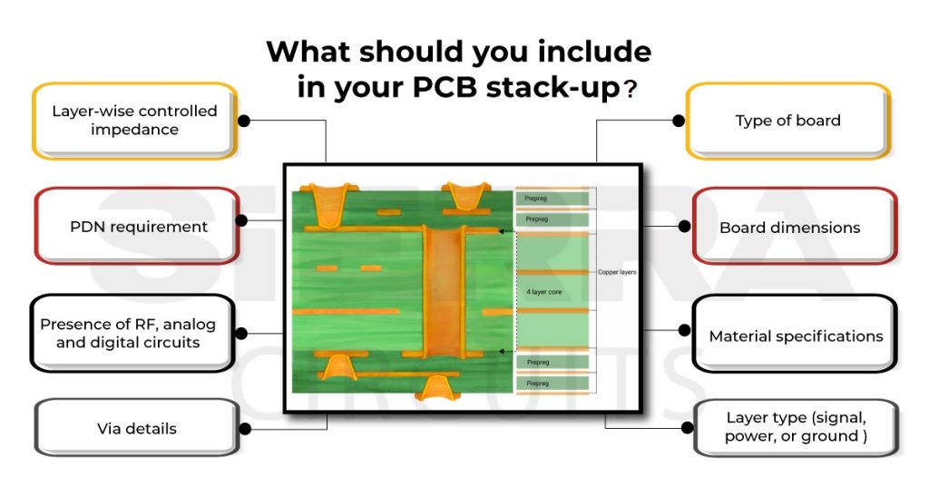
Clearly define the electrical and mechanical demands of your board. This includes:
- Type of board: HDI, hybrid stackup, high-speed, rigid, and rigid-flex
- Material specifications
- Number of signal layers and power layers
- Power delivery network (PDN) and its impedance characteristics
- Impedance values for high-speed traces
- Layer assignments and trace widths to maintain controlled impedance
- RF, analog, and digital circuit requirements (operating frequencies)
- Blind or buried via requirements
- Board dimensions and tolerances
- Special requirements for mounting holes or slots
- Class 2 and 3 requirements

Consult your manufacturer at an early stage to understand their capabilities and limitations. Get their insight on layer stack specifications like materials, thicknesses, and copper weights.
Discuss the cost and feasibility of producing your stack-up. Further, verify if it meets industry standards and regulations.
2. Understand the manufacturing tolerances before finalizing the layer stack
When evaluating manufacturing tolerances, pay close attention to layer-to-layer registration, finished board thickness, and controlled impedance.
Layer-to-layer registration: During manufacturing, the material undergoes an enormous amount of thermal and mechanical stress. This can misalign the layers and offset the vias. If the board is not symmetrical, it can even cause the board to deform or warp.
To avoid this, ensure that all the materials used have similar CTEs, especially if you are opting for a hybrid build-up with different laminates. A maximum of 50µm or 1.9685 mil tolerance is acceptable in layer-to-layer registration.

Finished board thickness: Fabricating a board to an exact thickness may not always be possible. There will be some variation in the specified and finished board thicknesses. Hence, consult your manufacturer to ensure the variation is within the limits to avoid issues during the final mounting process.

Board thickness tolerances are as follows:
| Board thickness | Tolerance |
|---|---|
| Less than 15 mil | ± 2 mil |
| 15 mils to 31 mil | ± 3 mil |
| 31 mil and above | ± 10% |
Controlled impedance: There can be a slight variation in the specified and manufactured impedance values. The standard tolerance for controlled impedance is ±10%. Sierra Circuits can fabricate circuit boards with a tolerance of ± 5% for controlled impedance.
If you are planning to build an IPC class 3 board, ensure that the dielectric thickness is a minimum of 2.56 mil with 2 plies of prepregs.
PCB Stack-Up Design Guide
12 Chapters - 55 Pages - 60 Minute ReadWhat's Inside:
- Design guidelines for HDI, flex, and hybrid stack-ups
- Stack-up representation in fab drawing
- DFM checks for layer stacks
- Characteristics of high-speed materials
- Manufacturing tolerances
- PCB stack-up examples with illustrations
Download Now
3. Use PCB layout design tools to build your stack-up
After finalizing all the specifications, build the layer stack using circuit board design software. The steps include:
- Create a new project and define the physical dimensions and shape of your circuit board (length and width, with specific cutout regions).
- Arrange layers to attain symmetry using a layer stack manager.
- Set the impedance profile requirement with the type (microstrip or stripline), target impedance, and tolerances.
- Define the required via type (through or microvia), aspect ratio, dimension, and connecting layers. You can also add back-drilling requirements.
- Configure the sub-lamination requirements, if needed.
- Run design rule checks and fix any errors or violations flagged.
- Advanced PCB design tools offer simulation and analysis of your circuit design, including stack-up. Perform signal and power integrity analyses to check the board’s functionality.
- Download Gerber or ODB++ files. Here, you can represent the layer stack details in cross-section drawings and tables. You can also include other special requirements and specifications in fabrication notes.

4. Repeating the same manufacturing process in high-volume production
Once your prototype is finalized, your design can be sent to mass production. During this, your manufacturer will scale up the process to build multiple boards at once. Repeating the same process from prototype to bulk production is one of the essential traits of a capable manufacturer. Hence, discuss and understand the high-volume production process of the fab house you pick.
Additionally, your stack-up should also be compatible with mass production, with readily available materials and a simplified design.
Use our Stackup Designer to expedite your design process. You can build and export your stack-up in IPC-2581 format in a go using this tool.

What are the most common stack-up mistakes?
The most frequent build-up errors are specifying impedance without complete dielectric details, using unbalanced layer arrangements, and overlooking fabrication tolerances. These oversights can result in expensive redesigns and production delays.
Other mistakes include:
- Missing or partial reference planes beneath high-speed signal layers.
- Copper weights are undefined or inconsistent with the impedance targets.
- Dielectric thickness incompatible with via aspect ratio limits.
- Impedance and trace width were calculated using an incorrect dielectric thickness.
- Fabrication tolerances are not specified for dielectric thickness, trace width, or impedance.
- Solder mask and surface finish thickness are not considered in the finished board thickness calculations.

Need help designing a PCB stack-up? Our engineering team can help you with material selection, controlled impedance routing, and DFM analysis.
You can book a meeting with our experts or call us at +1 (800) 763-7503.

5 design tips to build your PCB stack-up with signal integrity
Select the right materials, allocate sufficient signal and reference planes, and maintain controlled impedance to ensure signal integrity in your layout.
The following design guidelines will help you achieve the objective:
1. Select the right dielectric material
Allan Knox, Senior PCB Design Engineer at Sierra Circuits, explained,
“Choosing the right laminate is crucial, as everything starts with that. It determines your signal losses, clock settings, heat management, and power handling capabilities.”
While selecting the material, ensure that it meets all the electrical, mechanical, and thermal properties required for your design. For instance, opt for low-Dk material if you are building a board that operates at a higher frequency (in GHz). However, they can be expensive, so understand the trade-off.

Copper plane selection mainly depends on the current that flows through your board. If you’re working on a high-current board, you need to choose a thicker copper plane. To learn more, see the role of PCB trace current capacity in design.
2. Estimate the optimum number of signal layers
PCB stack-up is dependent on the number of signal layers present in the design. For instance, high-speed or high-power applications may require a greater number of layers compared to low-speed boards.
Low-pitch, high-pin-count complex devices like BGAs usually require a greater number of signal layers. Furthermore, signal integrity requirements like extremely low crosstalk may also require a higher number of signal layers.

Analog and digital signals will require separation between the two types and are likely to increase the number of signal layers.
3. Calculate the required number of ground and power layers
Using ground and power planes allows the designer to allocate signal layers purely for signal routing. They also reduce the DC resistance in the power and ground rails, thereby ensuring fewer DC voltage drops at the devices.
The ground layer is the plane of copper that connects the ground connection of the power supply. A power layer is a flat plane of copper that connects to the power supply rail.

The planes also provide signal return paths for time-varying and high-frequency signals. This helps to considerably reduce noise and crosstalk, thereby improving signal integrity. Power planes also improve the capacitive decoupling ability of the circuits. In addition, they also improve EMC performance by reducing EM radiation.
Read our article on 7 considerations for PCB power supply design.
4. Ensure uniform impedance throughout the high-speed traces
A uniformly controlled impedance is important for achieving good signal integrity. To attain the targeted impedance, you need to carefully design the trace geometry, including the trace width, spacing, and layer stack.
If the reference plane for the trace is not on the next layer over, the nearest copper feature can act as the reference and cause distortion. To avoid this, always have a solid ground plane right below the controlled impedance trace.

Always consider the trapezoidal effect of the trace while calculating the impedance.
5. Avoid placing adjacent signal layers to reduce EMI
Another key aspect of the layer stack design is the sequential layer arrangement. Here, you need to place alternating layers of signal, ground, and power planes to reduce EMI effects. Consider these guidelines to arrange the layers for good signal integrity:
- Place signal layers below the ground plane for tight coupling
- Keep a minimum distance between the power and ground planes
- Avoid placing two adjacent signal layers to avoid EMI issues
- Maintain symmetry in your stack-up to avoid manufacturing failures
- Don’t split the power plane, as it causes noise issues
- Place two adjacent power planes as far as possible to avoid unwanted coupling

To learn how proper layer orientation improves signal integrity and reduces EMI, read PCB layer orientation.
How the right stack-up can save your prototype
A well-designed PCB stack-up improves signal integrity, manufacturability, and overall board performance. The infographic below highlights how stack-up decisions can impact your prototype.

7 DFM guidelines to create reliable build-ups
- Tailor your stack-up based on:
- Signal speed and operating frequency
- Number of layers needed
- Current capacity and thermal needs
- Balance the copper distribution to prevent board warping during lamination.
- Place signal layers one dielectric layer away from the ground planes to minimize EMI in your boards.

The signal layer is placed one dielectric layer away from the ground plane. - Ensure your trace width/spacing and dielectric thicknesses align with the target impedance values (e.g., 50Ω, 90Ω).
- Group the signal layers based on their operating frequencies to maintain signal integrity.
- Consider copper plating, solder mask, and surface finish layers before finalizing the board thickness.
- Before establishing the final board thickness, check your CM’s tolerances (typically ±10% of the target thickness).
What stack-up details should be included in PCB fabrication notes?
Your fabrication notes should clearly define the stack-up requirements needed to manufacture the board accurately.
Include the following information:
- Total number of layers and layer names (e.g., Top, L2_GND, L3_Signal, Bottom)
- Clear identification of:
- Signal layers
- Power planes
- Ground planes
- Mixed layers
- Core and prepreg material types
- Material thickness of each layer (in mil or mm)
- Copper weight per layer (oz/ft² or μm)
- Finished copper thickness after plating
- Total board thickness and tolerances
- Target impedance values (e.g., 50Ω single-ended, 100Ω differential)
- Trace width/spacing for each controlled impedance line
- Impedance tolerance (e.g., ±10%)
- Stack-up drawing or cross-sectional view

What are the different types of PCB stack-ups?
Standard multilayer, flex, rigid-flex, and HDI are the most widely used PCB stack-up types. Each offers unique advantages.
Standard multilayer build-up
These stack-ups are fabricated in a single lamination cycle. It can accommodate more complex circuits when compared to single-layer boards. Due to a single lamination cycle, the board undergoes less thermal and mechanical pressure. Additionally, it does not require laser drilling. Hence, board production becomes more cost-effective with less turnaround time.

On the contrary, you can only implement through-hole vias, so there will be less utilization of space.
Flex and rigid-flex stack-up
They are usually built with a polyimide material, which offers flexibility. It also includes adhesives, stiffeners, and overlays. You can design the complete board with flexible material, or a part of it can be rigid. These boards are thin and flexible and are used in medical, aviation, and space applications.

HDI build-up for a compact board
HDI stack-ups are fabricated using a technique called sequential lamination. These boards feature microvias that have an aspect ratio of 0.75:1. This will help to increase the component and trace density. As the board is sequentially built, you can have a larger variety of design choices. It simplifies the design architecture.
In HDI, the number of ball grid arrays (BGA) or the highest pin count device determines the number of layers. Other factors affecting stack-up include the number of signal, power, and ground layers.
Microvia structures can greatly impact the manufacturing process since they directly affect the number of lamination cycles. Any layer on which a microvia starts or stops requires a sub-construction, and each sub-construction will require an extra lamination cycle.

During each lamination, the board will be exposed to thermal and mechanical stress. This will reduce the reliability of the board. It also increases the cost and manufacturing time. Hence, arrange the vias such that they undergo the least number of lamination cycles. A well-defined stack-up plan should also account for PCB scaling to offset predictable material shrinkage during lamination and ensure final dimensional accuracy.

HDI PCB Design Guide
5 Chapters - 52 Pages - 60 Minute ReadWhat's Inside:
- Planning your stack-up and microvia structure
- Choosing the right materials
- Signal integrity and controlled impedance in HDI
- Manufacturing considerations for higher yields
Download Now
Stack-up for high-frequency applications
Here, the signal loss in the material becomes crucial. Hence, the layer stack is built with a low-Dk material that offers the least signal distortion.
If there are limited traces that operate at high frequencies, then you can even opt for a hybrid stack-up where only selected layers are built with low-Dk material. RF circuits and high-speed circuits are also built with the same technology.

How do BGAs impact PCB stack-up design?
Ball grid arrays (BGAs) can affect layer count, routing complexity, increase heat generation, and introduce challenges in future repairs.
Let’s look at how BGAs impact PCB stack-up design.
1. Increased layer count
BGAs have 200 to 2500 pins; hence, you may require additional PCB layers to breakout these pins.
Consider these design recommendations when building a stack-up with BGAs:
- Design the stack-up such that each layer serves a specific purpose, whether it’s for routing signals, providing power, or grounding.
- Determine the required PCB stack-up layers by assessing the BGA pin count. The first two outer rows of the BGA can be routed on the surface layer without vias. The following two rows can be routed to the subsequent inner signal layer using dog-bone fanout for higher pitch BGAs (0.8-1 mm) and via-in-pad structure for lower pitch BGAs (0.4-0.5 mm). You can make use of our PCB Stackup Designer to quickly calculate the required number of layers, providing the pin count of the BGA.

- Utilize inner BGA layers for ground planes to reduce EMI.
- Designate specific layers to accommodate high-speed signals. This isolation prevents interference and maintains signal integrity.
2. Demands advanced routing solutions
Breaking out BGA pins calls for innovative routing techniques to ensure signal integrity. To accommodate intricate routing requirements, you may need to increase the layer count, impacting both cost and complexity.
Keep these design tips in mind to optimize escape routing:
- Implement dogbone fanout techniques to route traces from the BGA to nearby vias and then route the vias to their respective destinations. This reduces trace density under the BGA, minimizing the risk of crosstalk.

- Employ microvias that allow you to create more routing layers and help achieve shorter trace lengths. This simplifies the breakout process while maintaining signal integrity.
- Isolate the high-speed signals from others and reduce their length as much as possible.
- Implement controlled impedance traces to fanout the BGA pins. This reduces the risk of impedance mismatches during the trace-to-via transition.
- Incorporate a solid ground plane to ensure a proper signal return path.
- Allocate specific layers within the circuit for routing connections from the BGA. These dedicated signal layers, ground planes, and power planes provide clear pathways for connections.
3. Increased heat generation affecting PCB reliability
Effective thermal management is essential as BGAs with high pin density can lead to increased heat generation and impact the overall reliability of the circuit board. Below are several design tips to address thermal challenges in PCBs with BGAs:
- Implement thermal pads beneath BGAs to create direct heat transfer paths to thermal vias or ground planes for efficient heat dissipation.
- Incorporate a through hole via beneath the ball grid array and expose the vias at the bottom by eliminating the solder mask. This provides direct access to air, enhancing heat dissipation.
- Consider attaching heat sinks to the top of BGAs. Heat sinks enhance heat dissipation, especially in high-power designs that use heavy-copper stack-ups.
4. The compact nature of BGA introduces challenges in future repairs
Incorporating BGAs into your design can present challenges regarding future repairs, upgrades, and component replacements.
Here are some design tips to facilitate future upgrades and simplify repair processes:
- Incorporate test points facilitating testing during manufacturing or troubleshooting. Avoid test points directly under BGA components and leave a 5.08 mm (200 mil) gap around BGAs. This ensures a safe distance to accommodate testing requirements and minimizes the risk of mechanical stress on the solder connections.

- Implement a socket-based BGA where you can directly place a component without soldering. This also eases the replacement procedure if required.
- Provide comprehensive documentation that includes BGA-specific information, such as ball array configurations, pin count, and number of signal and ground pins for future repair and upgrade purposes.
Sample PCB build-ups
Here are a few samples of different types of circuit board build-up
Standard 4-layer stack-up

6-layer rigid-flex stack-up: 6 layers with 3rd and 4th layers as flex

Hybrid PCB stack-up: Stack-up made up of Rogers 4350 and Isola 370HR material for high-frequency circuits

HDI stack-up: 16-layer board with through-hole, buried, and staggered blind vias

Key takeaways:
- Employ PCB layout design tools to build your stack-up and conduct design rule checks to rectify any identified errors or violations flagged by the DRC.
- Opt for a low-Dk material if you are building a board that operates at a higher frequency (in GHz)
- Leverage ground and power planes for signal routing and reduced DC resistance.
- Copper plane selection depends on circuit operating current; for high-current boards, opt for thicker copper.
- Achieve target impedance by carefully designing trace geometry, including width, spacing, and layer stack.
- Rigid-flex stack-ups are usually built with a polyimide material, which offers flexibility.
- In HDI, the layer count is determined by the number of ball grid arrays (BGA) or the highest pin count device.
- Determine the required PCB stack-up layers by assessing the BGA pinout and I/O count.
- Utilize inner BGA layers for ground planes to reduce EMI.
- Collaborate with manufacturers early on to align specifications with capabilities.
Any mishap in the stack-up preparation can cause EMI and signal distortion in your design. If the errors are not identified during the design phase, you may have to discard the entire board. Hence, careful planning from the initial stage will help you build the right stack-up in the first attempt. If you require any assistance in building your layer stack, post your queries on SierraConnect. We’ll be happy to help you!

About Sushmitha V : Sushmitha V has a master's degree in power electronics and has over four years of experience in the PCB industry. Her areas of interest include circuit board manufacturing, assembly, IPC standards, and DFM/DFA practices.


Start the discussion at sierraconnect.protoexpress.com