


Contents

On-demand webinar
How Good is My Shield? An Introduction to Transfer Impedance and Shielding Effectiveness
by Karen Burnham
IPC-6012 defines the qualification and performance criteria for rigid circuit boards. It specifies how a board must be fabricated to meet reliability expectations. IPC-A-600 provides illustrations to verify if the requirements have been met. It is used during inspection and quality assurance.
PCB designers, quality engineers, or manufacturing leads must understand and apply these benchmarks to define fabrication protocols, align inspection processes, and verify board quality.
In this article, you’ll learn the differences between IPC-6012 and IPC-A-600, the latest updates and addenda to both standards, and their impact on printed board design, fabrication, and inspection.
Highlights:
- IPC-6012F, the latest revision, sets the requirements for back-drilled structures and microvia testing.
- It applies to single-sided, double-sided, multilayer, HDI, embedded, and metal-core boards.
- IPC-A-600 evaluates via quality, annular ring integrity, surface defects, and plating-related anomalies.
- IPC-9121 is a practical troubleshooting guide that outlines common fabrication issues, their root causes, and possible corrective actions.
What does IPC stand for?
IPC, the Institute for Printed Circuits, is a global organization serving the circuit board and electronics assembly industries since 1957. In 2025, the organization was renamed the Global Electronics Association.
The institute develops norms for circuit board materials, design, manufacturing, testing, qualification, and performance. It is accredited by the American National Standards Institute (ANSI). The headquarters is in Illinois, US, with additional offices worldwide.
What is the significance of IPC benchmarks in PCB design?
IPC regulations ensure that your board is manufacturable, reliable, and aligned with industry expectations.
As a designer, you need to be aware of the latest revisions. These specifications provide a common framework, ensuring you and your contract manufacturer use the same terminology and expectations. This reduces miscommunication, delays, and manufacturing issues.
For more, download the IPC Standards Handbook.
IPC Standards Handbook
7 Chapters - 110 Pages - 85 Minute ReadWhat's Inside:
- Clear breakdown of IPC standards for every stage of PCB development
- Design and DFM guidelines based on IPC-2221, IPC-7351, and IPC-J-STD-001
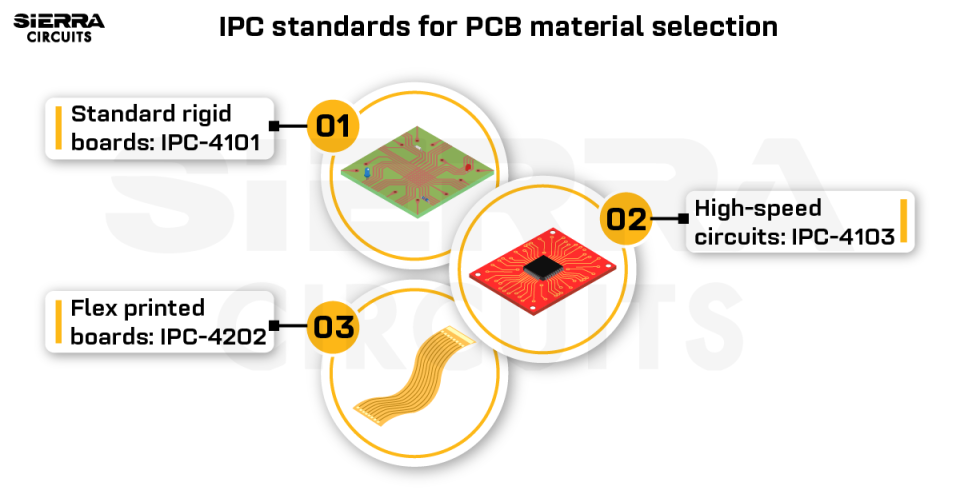
- Material selection guidance tied to IPC-4101, IPC-4202, and more
- Testing and inspection insights using IPC-A-600 and IPC-TM-650
- Best design documentation practices for seamless production
Download Now
What is IPC-6012?
IPC-6012 defines qualification and performance criteria for rigid PCBs. It applies to the following circuit board technologies:
- Single-sided and double-sided: With or without PTHs
- Multilayer: Standard and HDI
- Embedded: These have distributed capacitive planes and may have either capacitive or resistive components.
- Metal core (MCPCBs): These boards incorporate metal as a base material.

For more on MCPCBs, see the advantages of metal core printed circuit boards.
IPC-6012 is a part of the IPC-6010 series, which covers performance and quality norms for different board types as shown in the table below.
| IPC standard | Board type |
|---|---|
| IPC-6012 | Rigid |
| IPC-6016 | HDI |
| IPC-6017 | PCBs with embedded passive devices |
| IPC-6018 | High frequency (microwave) |
What IPC-6012 covers
The document discusses requirements related to:
- Dielectric materials and foils
- Board dimensions
- Conductor widths/thicknesses
- Structural integrity
- Via plating thickness
- Surface plating and surface finish coating criteria
- Solder mask coverage/thickness/curing specification
- Cleanliness
- Electrical, mechanical, and environmental parameters
- Thermal stress testing
- Quality assurance provisions (include test plans for quality conformance testing and acceptance testing frequency)

What is the latest version of the IPC-6012 standard?
As of March 19, 2026, IPC-6012F is the current revision, released in October 2023. It supersedes IPC-6012E, which was released in 2020.
The document introduces changes in areas such as:
- Back-drilled structures
- Surface finishes
- Copper wrap plating
- Solderability testing
- Plating overhang
- Marking inks
- Microsection evaluation of printed boards
- Thermal shock
- Performance-based testing for microvia structures
- Classification and requirements for PCB cavity structures

Fill out the form:
What are the addendums of IPC-6012?
IPC-6012FA (automotive), IPC-6012FS (space and military), and IPC-6012EM (medical) define additional requirements for high-reliability applications.
Let’s see each of these in detail:
IPC-6012FA (2024)
This addendum covers rigid circuit boards used in the automotive industry. These boards must withstand vibration and thermal stress cycles. It includes updated requirements for:
- Lifted land criteria
- Copper feature accuracy
- Solder mask thickness
- Dielectric removal and wicking
- Cleanliness criteria
- Suitability and reliability testing parameters
- Panels that are coated with solder mask

Read 10 automotive PCB design guidelines to learn class 3 design specifications for automobiles.
IPC-6012FS (2024)
It defines class 3 criteria for space and military applications. The addendum addresses boards designed to endure vibration, intense thermal cycling, and ground testing.
IPC-6012EM (2020)
This document focuses on medical-grade printed boards with ultra-fine features beyond standard HDI capabilities, including:
- Conductor width/spaces below 60 μm (2.3 mil).
- Via structures below 100 μm (4 mil).
Sierra Circuits utilizes self-learning automated scaling software (XACT) to ensure precision in HDI stack-up design. The system analyzes material type, thickness, and copper weight on each layer to accurately predict and compensate for material shrinkage.
Visit HDI PCB capabilities to learn more.
What is IPC-A-600?
IPC-A-600, also called IPC-600, sets the acceptability criteria for printed circuit boards across different product classes. It provides detailed visual illustrations of acceptable, marginal, and nonconforming conditions that can be observed on PCBs, both externally and internally.
This standard is widely used due to its visual approach and ease of interpretation. It is a preferred choice for inspection and certification.
The imperfections on the board’s exterior surface that can be seen and evaluated are called externally observable conditions. Internally observable conditions are features that need microsection evaluation of the specimen to check acceptability.
Some internal anomalies can project outside as voids or blisters. The boards should be sufficiently illuminated for effective evaluation. By following this process of inspection, it is determined whether the physical features of the final board are in accordance with the requirements.
IPC-A-600 serves as a visual interpretation guide for the minimum requirements defined in other standards, such as the IPC-6010 series and J-STD-003.
This document is designed to make sure that the board conforms to layer-to-layer spacing, the structural integrity of laminates, the physical dimensions of copper features, etching characteristics, and plating norms. It serves as a clear and accessible tool for examining printed boards, even for inspectors without extensive experience.
What does IPC-A-600 evaluate?
- Final PCB thickness
- Hole characteristics (e.g., size, plating quality)
- Solderability
- Dielectric thickness and solder mask errors
- Copper voids and plating anomalies
- Annular ring requirements and drill breakouts
- Surface and subsurface imperfections
- Defects in circuits

To fully align with IPC-A-600, you should consider the guidelines defined in the IPC-2220 series.
Designers and manufacturers can also agree on custom acceptance criteria, overriding the requirements when needed.
Another supporting document to the IPC-600 is IPC-9121. It is a useful troubleshooting document that discusses problems, causes, and possible corrective actions related to printed board fabrication processes.
At Sierra Circuits, we build circuit boards compliant with IPC, ISO, mil-spec, and ITAR standards.
To learn more, talk to a PCB expert: Book a meeting or call us at +1 (800) 763-7503.
What is the current revision of IPC-600?
As of March 19, 2026, IPC-A-600M is the latest revision, released in May 2025.
It includes expanded coverage on topics such as:
- Dielectric removal processes, including etch-back and smear removal
- Back-drilled structures
- Voiding and fill
- Microvia contact dimensions
- Wicking and delamination
- Surface plating criteria for edge board contacts, BGA pads, and wire bond pads
- Etched and ink-marking
- Printed board via fills
- Hole registration
- Additional examples supporting automated inspection technologies
IPC-A-600 acts as a useful tool for interpreting and understanding the results of automated inspection technology (AIT).
AIT is used to evaluate critical circuit board characteristics using:
- Automated X-ray inspection (AXI)
- Automatic optical inspection (AOI)
- Automated solder paste inspection (SPI)
- Automated laser test (ALT)
- Machine vision (MV)
To learn how to build reliable circuit boards, download the IPC Class 3 Design Guide.

IPC Class 3 Design Guide
8 Chapters - 23 Pages - 35 Minute ReadWhat's Inside:
- IPC guidelines for manufacturing defects
- IPC standards for assembly processes
- Common differences between the classes
- IPC documents to set the level of acceptance criteria
Download Now
What’s the difference between IPC-6012 and IPC-A-600?
IPC-6012 provides the performance criteria, whereas IPC-A-600 provides visual illustrations of these requirements, including examples of acceptable and unacceptable conditions.
The table below summarizes the differences.
| Parameters | IPC-6012 | IPC-A-600 |
|---|---|---|
| Purpose | Defines performance requirements | Illustrates assessment criteria with photos and details, showing acceptable conditions and what requires attention |
| Applicability | Rigid printed circuit boards | Rigid, flex, and rigid-flex PCBs |
| Scope | Contains circuit board design and manufacturing prerequisites | Supports inspection with clear photos and detailed descriptions |
In practice, both standards are used together; IPC-6012 defines what must be achieved, while IPC-A-600 confirms that those requirements have been met. This combination ensures consistency between fabrication and inspection, helping deliver reliable, high-quality circuit boards.
A correct understanding of these IPC requirements is essential at both design and manufacturing levels to avoid any misinterpretation. For example, the fab drawing should specify whether the copper weights mentioned are for the start or finished state. This prevents any rejections due to deviations during the quality check and dispatch of the circuit boards.
Visit our PCB certifications and registrations page to know the manufacturing and design standards we adhere to.
About the technical reviewer:
Gopal is an accomplished DFM/CAM engineer with over 30 years of experience in optimizing PCB manufacturing processes. At Sierra Circuits, he guides the planning and CAM teams to achieve the desired results. Gopal’s expertise in DFM guidelines and fabrication techniques enables him to build error-free circuit boards.
Need assistance with IPC classes? Post your queries on our forum, SierraConnect. Our design and manufacturing experts will be happy to help you.

About Pooja Mitra : Pooja Mitra is an electronics and communication engineer. With an experience of over three years in the PCB industry, she creates industry-focused articles that help electrical and PCB layout engineers.


Design to IC-6012.
Verify raw boards against IPC-600.