


Contents

On-demand webinar
How Good is My Shield? An Introduction to Transfer Impedance and Shielding Effectiveness
by Karen Burnham
Following IPC standards for PCB laminates makes it easier to choose dielectric materials that fit the specific needs of rigid, high-speed, and flexible boards. Standards like IPC-4101, IPC-4103, and IPC-4202 set clear benchmarks for key properties such as impedance control, thermal performance, and durability.
By using these standards as a guide, you can confidently pick materials that support both functionality and manufacturability. They also help you clearly communicate your requirements and ensure the chosen materials match your application needs.
Highlights:
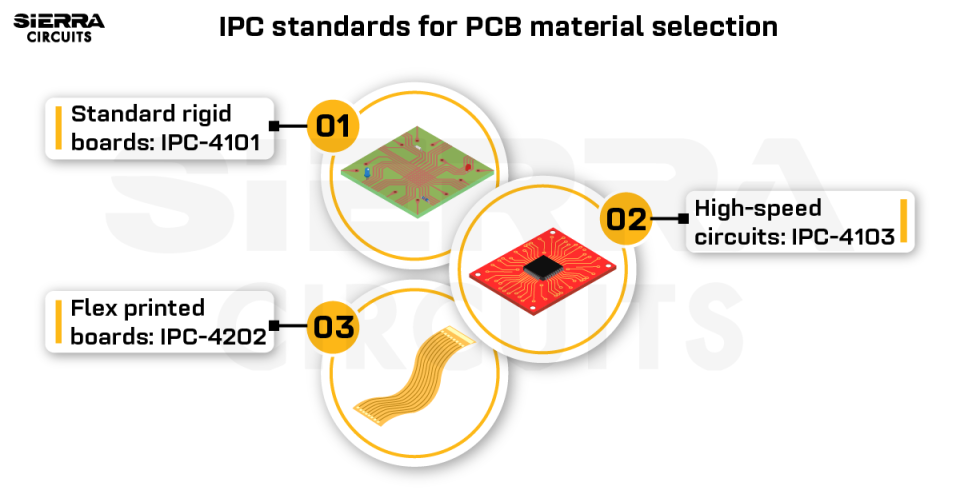
- IPC-4101 provides guidelines for rigid and multilayer PCB material selection.
- IPC-4103 focuses on high-speed laminates for RF/microwave and digital circuits.
- IPC-4202 specifies flexible dielectric materials requirements for dynamic and static applications.
In this article, you’ll learn the key IPC standards for PCB laminates and the practical factors to consider when choosing dielectrics for your design.
1. IPC standards you need to know for choosing circuit board materials
Selecting the right dielectric materials is critical for ensuring the electrical, thermal, and mechanical reliability of PCBs. To establish consistent benchmarks for material performance, IPC has developed a series of standards that define material properties, qualification methods, and documentation practices.
These standards help designers, manufacturers, and suppliers align on the specific material requirements needed to meet the demands of each design.
1.1 IPC-4101 for rigid and multilayer PCB base substrates
It is the key guideline for specifying cores and prepregs used in rigid PCB fabrication. The standard introduces a slash-sheet system that defines specific material types and their required properties.
Slash-sheet system in IPC-4101
The standard employs a slash sheet numbering system that precisely defines material requirements. This approach ensures consistency across manufacturers and prevents ambiguity in laminate specifications.
When documenting material requirements, refer to the appropriate slash sheet rather than commercial product names. For example, IPC-4101/126 slash sheet includes material specifications for woven E-glass reinforced epoxy laminates and prepregs.
Lead-free laminates listed in IPC-4101
Lead-free soldering calls for materials with enhanced thermal properties to withstand higher processing temperatures.
| Slash sheet | Material type | Fillers |
|---|---|---|
| IPC-4101/99 | Epoxy-based, Tg ≥150°C, Td ≥325°C | Inorganic |
| IPC-4101/124 | Epoxy-based, Tg ≥150°C, Td ≥325°C | No filler |
| IPC-4101/101 | Difunctional epoxy-based, Tg ≥110°C, Td ≥310°C | Inorganic |
| IPC-4101/121 | Difunctional epoxy-based, Tg ≥110°C, Td ≥310°C | No filler |
| IPC-4101/126 | High-performance epoxy-based, Tg ≥170°C, Td ≥340°C | Inorganic |
| IPC-4101/129 | High-performance epoxy-based, Tg ≥170°C, Td ≥340°C | No filler |
Material tests covered in IPC-4101
IPC-4101 defines test methods for qualifying materials, ensuring consistent evaluation across different suppliers. These tests include:
- Thermal analysis for Tg and Td determination
- Time-to-delamination tests at various temperatures
- Physical and mechanical property evaluations
- Environmental stress testing
By choosing materials certified under IPC-4101, you ensure they have passed rigorous testing and meet strict industry specifications.
Download our handbook to learn all key IPC standards for PCB design and manufacturing.
IPC Standards Handbook
7 Chapters - 110 Pages - 85 Minute ReadWhat's Inside:
- Clear breakdown of IPC standards for every stage of PCB development
- Design and DFM guidelines based on IPC-2221, IPC-7351, and IPC-J-STD-001
- Material selection guidance tied to IPC-4101, IPC-4202, and more
- Testing and inspection insights using IPC-A-600 and IPC-TM-650
- Best design documentation practices for seamless production
Download Now
1.2 IPC-4103 for high-speed and RF laminates
IPC-4103 focuses on materials built for high-speed signal transmission and RF/microwave PCBs. It covers clad and unclad plastic laminates and bonding materials.
Materials qualified under IPC-4103 are known for tight dielectric control and enhanced high-frequency performance.
What matters when selecting high-speed materials
High-frequency materials must maintain consistent electrical properties across their operating frequency range. According to IPC standards for PCB laminates, you need to consider:

Dielectric constant stability: IPC-4103-qualified laminates like Rogers RO4350B or Isola Tachyon 100G exhibit minimal Dk variation, typically within ±0.05 over 1 to 20 GHz.
Dissipation factor: Lower Df (<0.004) reduces signal loss at high frequencies. For example, Panasonic Megtron 6 has a Df of ≈0.0022 at 10 GHz, making it suitable for high-speed designs.
Controlled impedance capability: Materials used for controlled impedance designs must offer tight Dk tolerances, low Df, and consistent thickness across layers. This helps prevent impedance mismatches that could lead to reflection, signal distortion, or loss.
Isotropic properties: Isotropy is a material’s mechanical, thermal, and electrical characteristics that are uniform in all directions (x, y, and z axes). High-isotropy materials like PTFE laminates deliver more predictable and reliable performance under varying environmental and electrical conditions.
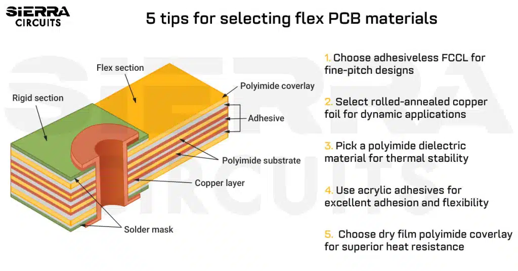
1.3 IPC-4202 for flexible dielectrics
IPC-4202 defines the requirements for flexible dielectric materials used in flexible and rigid-flex PCBs.
Unlike rigid laminates, flex substrates must withstand repeated mechanical stress, bending, and folding while still maintaining electrical integrity.
This standard sets specifications and test methods to ensure these materials deliver mechanical flexibility, thermal stability, and electrical performance across diverse applications.
Slash-sheet system in IPC-4202
Like IPC-4101, IPC-4202 employs a slash-sheet system to define specific material categories. Here are a few examples of slash sheets with their typical uses:
| Slash sheets | Material type | Reinforcement | Typical use |
|---|---|---|---|
| IPC 4202/1 – E1E2 | Polyimide (E) | Non-reinforced film (1) | Thin polyimide for single/double-layer flex |
| IPC 4202/2 – E3E3 | Polyimide | Woven reinforcement film (3) | Reinforced polyimide for increased strength |
| IPC 4202/3 – A1A2 | Polyvinylfluoride (PVF, A) | Non-reinforced film (1) | Low-cost flexible dielectric |
| IPC 4202/4 – C1C2 | FEP fluoropolymer (C) | Non-reinforced film (1) | High-temperature applications |
| IPC 4202/5 – D3D4 | PTFE (D) | Woven reinforcement (1) | Ultra-low loss for RF/microwave flex |
Decoding slash sheets in IPC-4202
A typical slash sheet code has below format:
IPC-4202/<sheet> – <dielectric><reinforcement><reinforcement type><thickness>
- Dielectric type is represented by alphabets: A = PVF, B = PET, C = FEP, D = PTFE and E = polyimide
- Reinforcement is represented by numbers: 1 = non-reinforced, 2 = nonwoven, 3 = woven, 4 = combination woven + nonwoven
- Reinforcement type (letters): A = glass, B = polyester, C = aramid, etc.
- Thickness (number/letter code): 2 for 50 µm, 1 for 25 µm, etc.
Example:
IPC-4202/ sheet – B2B4: Nonwoven polyester-reinforced PET with 50 µm thickness
- Dielectric: PET (B)
- Reinforcement method: nonwoven (2)
- Reinforcement type: polyester (B)
- Thickness: 50 µm (2)
Use this tool to quickly filter and select laminates based on IPC slash sheets for your specific PCB design needs.

Criteria for selecting the right flex dielectric materials
IPC-4202 specifies key properties to ensure reliability in dynamic environments. They include:
- Elongation and flexibility: Flex laminates should exceed 30% elongation to survive repeated bending.
- Peel strength: Minimum of 6 lbs/inch to prevent delamination under mechanical stress.
- Dimensional stability: Less than 0.1% shrinkage during thermal cycling to maintain trace alignment.
- Thermal endurance: Must withstand high soldering temperatures without cracking, curling, or delaminating.
Testing and qualification methods
IPC-4202 references IPC-TM-650 test methods to evaluate:
- Flexural endurance (bend and crease tests)
- Peel strength of copper foils
- Moisture absorption and resistance
- Dielectric breakdown voltage
- Dimensional stability under thermal cycling

These tests simulate real-world stress conditions, ensuring that flexible circuits can perform reliably in wearables, foldable electronics, medical devices, and aerospace systems.
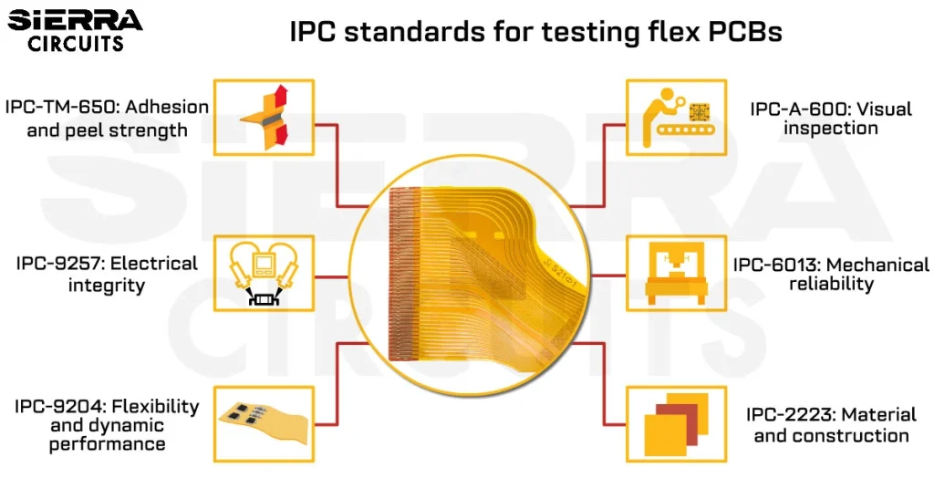
For more on flex PCB testing, see IPC standards and guidelines for flex PCBs.
2. What are the factors that impact PCB material reliability?
When choosing materials, fundamental properties like Dk, Df, Tg, and CTE are just the beginning. Advanced applications require a deep understanding of how a material behaves under specific operating conditions.
This includes signal integrity at high frequencies, thermal cycling reliability, manufacturability for complex designs, and compliance with environmental standards like RoHS and REACH. These concepts are discussed below.
2.1 Electrical behavior at high speeds
Above 5 GHz, materials must maintain stable electrical properties and low loss to preserve signal integrity.
Dk variation with frequency

Lower Dk values (<3.5) reduce signal distortion. Materials should maintain a stable Dk across a wide frequency range; variations can cause phase distortion and signal skew.
Df behavior in the GHz domain
Higher Df materials (e.g., standard FR-4 with Df ≈0.02) cause signal attenuation. For RF/microwave designs, Df <0.005 is preferred to minimize loss.
IPC-4101 slash sheets specify Dk and Df values at standard test frequencies (1 MHz, 1 GHz, or 10 GHz).
Example: IPC-4101/126 specifies Dk ≤3.7 and Df ≤0.009 at 1 GHz.
Copper surface profile and signal loss
A rough copper surface increases insertion loss at higher frequencies. IPC-4562 recommends very low profile (VLP) copper for high-speed PCBs.

For more, see copper for PCBs.
2.2 Thermal stability in extreme conditions
High-temperature environments demand PCB materials that can maintain mechanical and electrical integrity under prolonged thermal stress. Hence, properties like thermal conductivity (k), Tg, Td, and CTE become critical.
Thermal conductivity for power-intensive applications
Materials with higher thermal conductivity (e.g., metal core PCBs or ceramic-filled laminates) are favored in power electronics.</p>
IPC stand
ards for PCB materials do not prescribe a minimum thermal conductivity, but materials with k greater than 1 w/m·K (e.g., ceramic-filled laminates) are suitable for applications such as motor drives, power supplies, or automotive ECUs.

Tg, Td, and lead-free compatibility
High-Tg materials (typically above 180°C) are critical for PCBs operating in harsh environments or undergoing lead-free soldering. IPC-4101 defines Tg testing methods such as dynamic mechanical analysis and thermomechanical analysis.
Td indicates thermal reliability and should exceed 300°C to withstand lead-free solder reflow (260°C peak). IPC-4101 and IPC-4103 provide typical Td values measured using thermogravimetric analysis (TGA).
The IPC-4101 standard also specifies thermal parameters like T260, T288, and T300, which represent the duration a material can endure specific temperatures without degradation.

CTE and solder joint reliability
Mismatched CTE values stress solder joints during temperature cycling, especially in multilayer circuit boards. The CTE along X and Y axes should closely match copper’s CTE (~17 ppm/°C), while the Z-axis CTE must be kept low to prevent plated through-hole failures.
IPC-4101 recommends measuring CTE in all three directions. Specifically, Z-axis CTE should stay below 70 ppm/°C in the temperature range 50-260°C to preserve plated through-hole integrity and reduce barrel cracking.
2.3. Manufacturing compatibility
Sequential lamination
IPC-4101 specifies that materials must have a stable Tg and flow consistency across sequential lamination cycles (2-3 cycles typical for HDI designs). No-flow prepregs should be qualified under IPC-4101/43 or IPC-4101/26 for reliable rigid-flex bonding.

Dielectric thickness control
The selected material should withstand the expansion during lamination to achieve the desired impedance. IPC-4101 defines thickness tolerances as ±10% for cores and ±15% for prepregs.
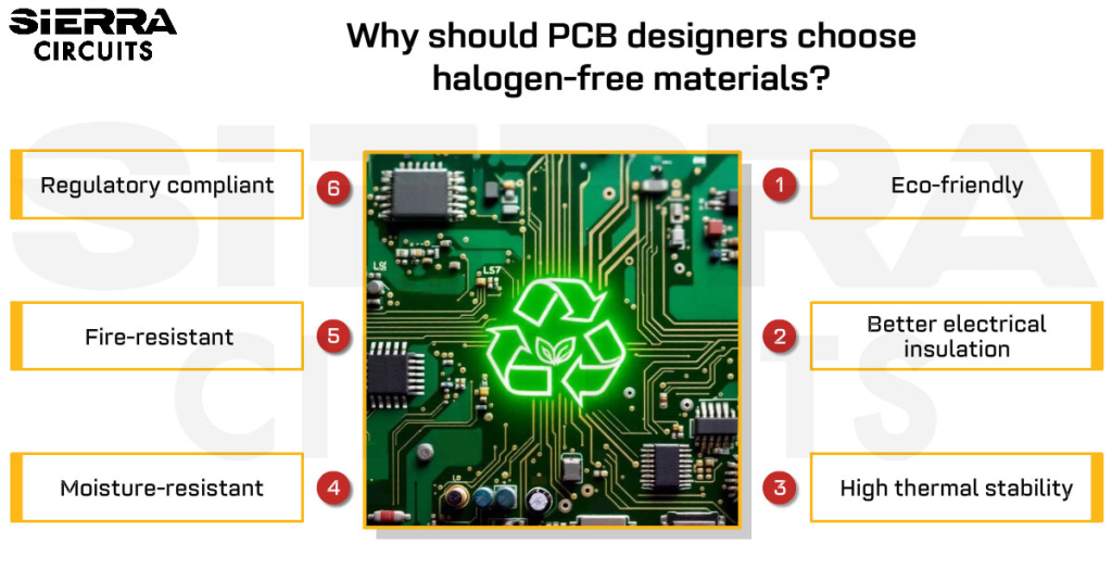
2.4. RoHS/REACH and UL compliance
Materials must meet flammability standards (UL 94V-0) for high-reliability designs. Halogen-free PCB material options are available under IPC-4101B sheets for EU compliance. IPC-1752 establishes the standards for material traceability and auditability.
Sierra Circuits fabricates and assembles high-quality circuit boards with a quick turnaround time. Visit our rigid PCB manufacturing capabilities to learn more.
2.5. Testing and quality control
IPC-TM-650 provides standardized test methods for dielectric breakdown, peel strength, thermal shock, and moisture resistance.
For multilayer boards, each layer type (core and prepreg) must meet specific IPC-4101/4202 requirements. Laminate flow consistency is tested using IPC-L-107 test coupons.
See design for testing guidelines for PCB manufacturing for DFT tips.
3. PCB material examples with their use cases
| Materials | IPC Standards | Tg (°C) | Dk @ 10GHz | Df @ 10GHz | Z-CTE (ppm/°C) | Use case |
|---|---|---|---|---|---|---|
| FR-4 (4101/21) | IPC-4101 | ~130 | 4.3 | 0.02 | 180 | Consumer electronics |
| FR-4 (4101/26) | IPC-4101 | ~180 | 4.2 | 0.015 | 70–90 | Industrial/Automotive |
| Megtron 6 | IPC-4103 | >200 | 3.6 | 0.0022 | ~60 | 100G backplane, routers |
| RO4350B | IPC-4103 | ~280 | 3.48 | 0.0037 | ~40 | 5G RF modules, radar |
| Polyimide (4202/11) | IPC-4202 | >250 | 3.2–3.5 | ~0.01 | ~50 | Aerospace, dynamic flex |
Download our eBook to learn how to pick the right materials for your PCB designs.

PCB Material Design Guide
9 Chapters - 30 Pages - 40 Minute ReadWhat's Inside:
- Basic properties of the dielectric material to be considered
- Signal loss in PCB substrates
- Copper foil selection
- Key considerations for choosing PCB materials
Download Now
4. Flowcharts for choosing the best circuit board base materials
We’ve created six quick flowcharts based on IPC standards for PCB laminates. They cover specific design needs from thermal performance and electrical properties to layer count, dimensional stability, hole plating, and single-sided board requirements.
Flowchart 1: Laminates with better thermal performance
Flowchart 2: Materials for improved electrical properties
Flowchart 3: Substrates for boards with more than 10 layers
Flowchart 4: Boards requiring higher dimensional stability
Flowchart 5: PCBs with punch-plated through holes
Flowchart 6: Dielectrics for single-sided boards

Key takeaways
- Always stick to the IPC standards for PCB laminates when picking materials for your designs. Consider the material selection parameters (Dk, Df, Tg, Td, CTE), but always evaluate performance under real operating conditions.
- Match material properties with application type: high-speed, high-power, or dynamic flex.
- Rely on IPC slash sheets instead of vendor brand names for consistency and compliance.
- Confirm testing, certification, and environmental compliance before finalizing a laminate.
Selecting the right PCB material goes beyond datasheets; it requires aligning electrical, thermal, and mechanical properties with application demands. IPC-4101, IPC-4103, and IPC-4202 provide the framework to make reliable and compliant material choices. By following these standards, you ensure your PCB design delivers consistent performance and long-term reliability.
Need guidance on which IPC standard to follow? Post your queries on SierraConnect. Our PCB experts will answer them.

About Sushmitha V : Sushmitha V has a master's degree in power electronics and has over four years of experience in the PCB industry. Her areas of interest include circuit board manufacturing, assembly, IPC standards, and DFM/DFA practices.


Start the discussion at sierraconnect.protoexpress.com