


Contents

On-demand webinar
How Good is My Shield? An Introduction to Transfer Impedance and Shielding Effectiveness
by Karen Burnham
Aviation and aerospace is a hot topic right now. The number of aircraft is likely to double in the next 20 years and space is slowly becoming accessible to tourists. And SpaceX will fly you across the globe in less than one hour pretty soon.
This means that the number of circuit boards for these applications has already started to increase. Facing a huge demand, designers have to learn the specific rules to design a board for aviation and aerospace. And manufacturers have to be capable of meeting their customers’ needs.
During PCB West, Sierra met with Paul Cooke, Director of Field Application Engineering for an aviation and aerospace company. Expert in this field, he told us about the top must-knows that designers should keep in mind when designing for aviation and aerospace.
The Aviation Must-Knows
1. Reliability is the key
For space and aerospace, the primary goal is to build reliable products. An aerospace customer or satellite customer is going to expect their electronics to last 15 to 20 years with zero failure. So electronics’ longevity and zero failure are key.
To improve reliability in circuit boards, you really need to start at the PCB fabrication and design itself. The first thing the designer needs to do is to design the board to be reliable. Don’t use bleeding edge technology. Use standard technologies that we know are proven reliable, are not going to fail.

2. Use heavy copper
Most space applications use very heavy copper, much heavier than 2-oz copper. I see a lot of designs with up to 5-oz copper. I see some 20-layer products with 20 layers of 4-oz copper. How they manage heat in space is basically through dissipation. Efficient aerospace PCB thermal management is carried out by employing heavy copper designs, incorporating lot of thermal vias, and using chassis to dissipate heat. Because remember, energy in a satellite is key. You can’t have fan-cooled systems, so you need to use the natural properties of the copper itself as part of your heating and cooling strategies. But it is a challenge, and as you know, building very heavy copper boards is not easy. Plus, it is going to be in a material, like a polyimide, which is a much more difficult resin system to work with, so it brings its own challenges to meet the requirements.
Refer to our post on PCBAs for aerospace thermal control system to learn about the heat dissipation methods and critical aspects of boards such as design considerations, material selection, etc.

3. Material: Polyimide
Polyimide is probably 95% of applications. It depends on the satellite. If it is a 15 to 20-year geostationary satellite, it is going to require polyimide. Some of the lower-orbit satellites that maybe are only useful for two to three years, can use other materials. Companies, like Rogers, are moving into producing materials that are now becoming attractive to the customers who are doing the space application.
Also read, why are flex PCBs used in satellite applications to learn how flexible circuits reduce weight and and making more space-efficient.
4. Redundancy
There is a lot of redundancy built in an aircraft to make sure everything will be alright in case of a lightning strike, for instance. Typically, there is more than one system so you can switch over to another one in case of a failure. And the way that aerospace works is that they are not ever both supplied from the same supplier. If there is ever a defect, you don’t want to run the risk of having the same defect on the backup system. There is a lot of redundancy built within the aircraft.
Engines could die, and the aircraft can still fly on one engine. Same in the electronics. If one board fails, there is typically a backup for that system as well.

5. Choose a standardized process manufacturer
When you choose a manufacturer to build your circuit boards for aviation and aerospace, make sure each process is standardized, repeatable. You have to have the process controls and measurements to ensure that the repeatability is 100% all the time. Customers can ask for data from the fabricator’s processes. A lot of satellite customers will ask for DPA-type analysis, basically, destroying good product to prove you have the right plating thicknesses, etc., all the way down to SPC process control analysis for all your different processes.
The design has to be designed to be reliable, and the fabricator needs to be set up to build it to have reliable processes as well.
6. Forget about RoHS
The RoHS initiative in defense, aviation and aerospace is never going to apply. One reason is that aerospace is probably never going to move away from leaded HASL. The risk is really too high. The risk of moving to a different surface finish, moving to a different SMT, increased temperatures, is really adding additional potential risk to aerospace products. I deal with most of the aerospace customers on a regular basis, and there is absolutely nothing on the horizon to look at having a RoHS type initiative within aerospace. It will always be HASL.
You can use different surface finish. You can use ENIG, for instance, but on the assembly process, you need to use leaded materials.
7. Encapsulated electronics
In an aircraft, most of the electronics, like the engines, sit in an exposed environment. The only electronics that are internal would be your entertainment systems, all the galley lighting systems, etc. The cockpit is a controlled environment as well. However, there is no differentiator between internal and external fuselage. You build the electronics the exact same way. They have to be encapsulated and controlled.
Fuselage, engine, and wing electronics are basically encapsulated in hermetically-sealed boxes. So the boards themselves are not exposed to any elements. But they are exposed to temperature and heat and cold cycling on a daily basis.

8. Testing, testing and more testing
Electronics have to go into a whole set of different testing requirements to make sure they won’t fail. A lot of satellite customers have their own vacuum chambers in which they can temperature cycle their products. They have to mimic things like zero-gravity in a vacuum, and they need to go from -50 to +125 degrees, depending on whether they are working on a low-orbit or geostationary satellite.
On the aviation side, if you imagine an engine controller on an aircraft, and one of them is based up in Alaska and a similar aircraft is based in the desert in the Middle East, now you can see the massive temperature changes. You need to make sure that the aircraft can handle it when it moves from one of these environments to another. When an aircraft gets up to 10,000 feet, it is sitting at -50 degrees, which means any exposed electronics has to be able to withstand that temperature. And obviously, it will face an elevated temperature when it lands on the ground. Aircraft have to cycle through these temperatures multiple times per day.
So when you are building a circuit board for the aviation and aerospace industry, it comes with a whole set of testing loops that you need to jump through to prove the design is reliable. You need to be able to manufacture a reliable design for these types of environment.
To learn about standards that apply to aviation and space applications, see aerospace and defense PCB standards designers should know.
9. Don’t be afraid of paperwork
IPC 6012DS is a well-known document that Military and Space requires. It is basically an enhanced IPC Class 3. Your release requirements, your quality requirements, minimum plating, etc., are elevated within these specifications.
Paperwork is huge in aviation and aerospace. The amount of quality control, testing, reporting, micro-section analysis, FAIRS, etc. is very strict. It is even stricter for satellite customers who just take it to one more level. Normally, you might do 100% micro-sectioning for IPC Class 3. Some satellite customers are at 200% micro-sections. They just want to make sure everything is exactly built to the way they want it to be and their own specifications are above and beyond even what IPC Class 3A would be. They are very stringent on design rules, they are very stringent on process control, and release, etc.
See what Christopher Young has to say about aerospace PCB design challenges.
For more information on design rules, check with our DESIGN SERVICE team.
We build your aerospace PCB in Silicon Valley
Sierra has been working with the giants of the aerospace industry for years: we know all about your requirements! Here are four reasons why we won’t fail you and your space board:
1. OUR CAPABILITIES
Sierra helps aerospace companies build their high-speed PCBs from the development stage and the critical non-flight stage to the perfect flight board.
We manufacture Class 3 high-density interconnect (HDI), flex, rigid and rigid-flex boards from 1 to 24 layers.
Control your impedance
We can offer +/- 5% ohms for controlled impedance.
Our engineering team can help you establish an error-free stack-up and control your impedances when you specify the target ohms on each layer. Standard tolerances for controlled impedance are +/- 10% ohms but we can offer +/- 5% ohms when you come to us at an early designing stage.
You can watch our How To Control Your Controlled Impedance video for some useful tips and download our Controlled Impedance Design Guide.
Our most used materials for space PCBs are Isola 370HR and Nelco. They both have a very good resistance in high-temperature areas and therefore meet the Class 3 requirements.
Cross-sections all around
We do cross-section testing to prevent potential failure points.
Because it is essential to control the quality of your product to prevent potential failure points, we do cross-section testing. We cut out a small part of the board – which we call a test coupon – and check multiple aspects to ensure that we meet your quality requirements.
And good news: we do assembly too. No more delays, hassle and miscommunication between different vendors, we take great care of your board from layout design and manufacture to assembly.
We use our flying probe machine to electro-mechanically control the components in assembly. We perform open and short circuit testing, we measure the component values (resistor values of .1W – 100MW, caps value from 1pF – 100mF, and inductance values from 1uH – 10H can be checked by our machine), we test component placement and polarity, and last but not least, we identify missing components.
Here is your perfect flight board.
2. DESIGNING FOR AEROSPACE
Our engineers and PCB designers layout and design aerospace boards on a regular basis. Greg Albers, one of Sierra’s PCB designers, said, “When you design a board for the space industry, you have a certain number of rules and written-down standards to follow. You have to make a robust board that will resist the g-force vibrations, thermal issues, and even the plasma effect because, in space, the board could completely liquefy.”
Robustness is the keyword for aerospace.
Robustness is the keyword for aerospace. At Sierra, most of the boards we deliver for this industry feature through-hole vias with a diameter of minimum 21 mils, and traces with a minimum width of 8 mils, with two to four ounces of inner layer copper. “One particularity when designing for space, Greg added, is that you put a pad on every layer even if you don’t need one. It makes the PCB more robust – you don’t want it to crack up there!”
3. OUR SERVICE
Perfection rhymes with administration.
At Sierra, we know that reaching perfection rhymes with administration, which is why we deliver our customers with all the necessary traceability and tolerance documents for your incoming inspections.
Sierra’s Aerospace Account Manager Michael Cussary explained, “When most customers only ask for a couple of documents, we can be required to deliver up to ten traceability and tolerance certificates for the aerospace industry. They need to keep track of information such as lot codes, expiration dates, actual cure times, and so on.”
Below is a non-exhaustive list of the documentation we are used to providing:
– IPC J-STD-001E
– Calibrated tools used during manufacturing record
– AOI Report or Visual Inspection Report
– Flying Probe or In Circuit Testing Report
– Ionic Cleanliness Test Report
– Certificate of Conformance
– Material Specifications
– Reflow Profile Copy (included with First Article)
– Photo Requirements
– First Article Inspection Report
4. OUR CERTIFICATIONS
Sierra has been a premier manufacturer of PCBs since 1986. We believe that repeat business from our customers best illustrates our high standards and commitment to excellence. That is the metric we are the proudest of and what we measure ourselves by.
And, of course, we have all the required certifications to build your aerospace PCBs:
– ITAR Registration Letter
– ISO 9001:2015 Certificate
– IPC-A-600
– IPC Class 3
Learn more about all of our certifications.
VISIT SIERRA
We regularly invite PCB designers, engineers, and anyone interested to visit our facility in Sunnyvale, California. During your behind-the-scenes tour, we will show you our manufacture, our assembly, our machinery, and what we do to differentiate ourselves from other PCB shops to produce high-quality boards.
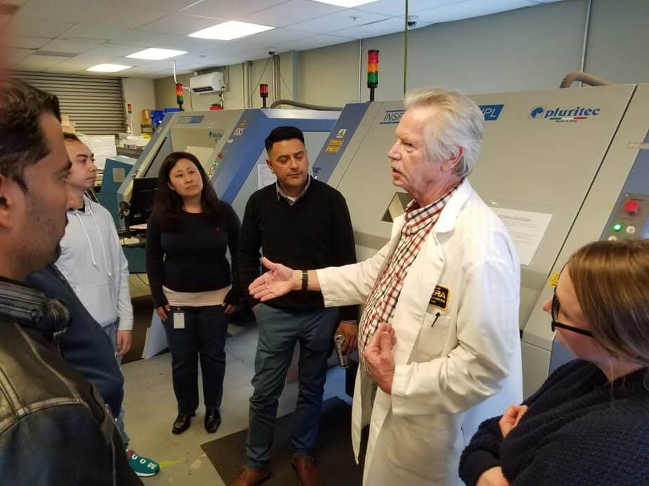
Call us at (408) 735-7137 to book a tour!


