Contents

On-demand webinar
How Good is My Shield? An Introduction to Transfer Impedance and Shielding Effectiveness
by Karen Burnham
When you’re designing aerospace and aviation PCBs, you need to consider structural strength, corrosion resistance, heat dissipation, and electrical capabilities.
Reliability is a key aspect of aerospace and aviation boards since they operate at high altitudes. They are expected to operate efficiently in harsh environments while adhering to tight tolerances.
To achieve this, you need to select materials and components that can withstand high temperatures and vibrations.
For instance, passive components have different CTEs, which can lead to thermomechanical stress. To overcome this challenge, select ceramic and thick film components as they are capable of handling high temperatures.
In this article, you will learn design considerations and industry standards to build reliable aerospace PCBs.
14 aerospace PCB design rules
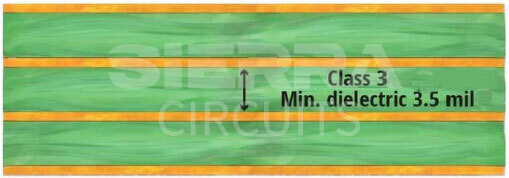
1. The minimum thickness of the dielectric material should be 3.5 mil. This provides sufficient mechanical strength to the board.
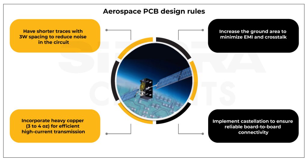
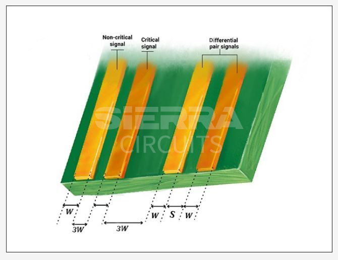
2. Include shorter traces with sufficient spacing between them to reduce the noise in your circuit. Ideally, the clearance between the traces should be 3W, where W is the trace width.
3. Incorporate heavy copper (3 to 4 oz) to ensure higher current carrying capacity. Additional cushioning can help your board to withstand undue spikes.
4. Aviation and aerospace circuit boards should be capable of withstanding up to 2000 cycles at temperatures ranging from -40°C to 145°C. To achieve this, consider the following guidelines:
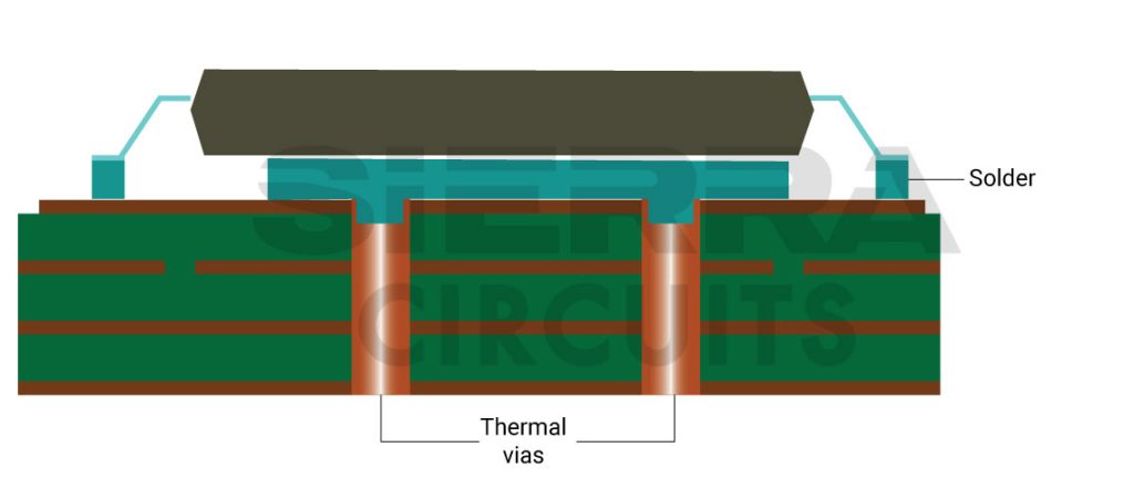
a. Design effective techniques such as heat sinks, thermal vias, and cooling fans to dissipate the generated heat.
b. Employ dielectric materials with high Tg, such as Isola FR408HR, Isola P95, Isola Astra, Rogers RO4003C, and Nelco N7000-2HT.
c. Heavy copper traces aid in transferring heat by conduction and convection methods.
d.Pre-tin the stranded and braided wires to increase solderability. It is the process of coating solder around a stranded electrical wire before actually soldering the wire.
To learn more about heat dissipation techniques, see aerospace PCB design tips for efficient thermal management.
5. Opt for HASL, Gold, and ENIG surface finishes for better soldering, longer shelf-life, and preventing outgassing issues.
6. Use conformal coating to safeguard the circuit board against heat, humidity, water, and vibrations. Apply an acrylic-based spray after conformal coating to get additional protection from contamination or accidental short circuits in the circuit board.
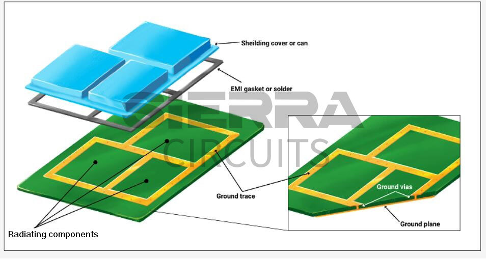
7. Increase the ground area as much as possible to reduce the EMI and crosstalk in your design. An aluminum enclosure as a physical shield also helps in mitigating electromagnetic noise.
8. Choose press-fit components that are soldered to reduce vibrations.
9. Fill vias with conductive or nonconductive via filling to keep solder and other impurities out of the through-hole and improve structural support to the pad. The conductive filling also helps to enhance electrical and thermal conductivity.
10. Implement castellation if you’re connecting your board to an external circuit board. This ensures good electrical bonding between the two circuit boards.
11. Isolate the high-frequency components from the low-frequency components, as the waveforms created by the high-frequency components can create noise and reduce signal quality.
12. Have a minimum internal annular ring size of 1 mil and a minimum external annular ring size of 2 mil. The minimum diameter shouldn’t be less than 1.96 mil, even if the holes aren’t centered.
13. Drill-to-copper clearance should be 8 mil.
14. Set the clearance distance depending on the peak operating voltage and surrounding temperature. Insufficient clearance may raise transient overvoltage events and result in arcing. Adhere to the latest version of IPC-2221, a generic standard to decide on clearance values for a high-voltage circuit.
To learn the ways to overcome common aerospace circuit board design hurdles, see aerospace PCB design challenges by Christopher Young
Industry standards for aviation and aerospace PCBs
- AS9100D: Provides a list of the QMS requirements for suppliers to the aerospace industry.
- AS9101E: Sets guidelines for auditing QMS.
- AS9102B: Jots down first article inspection (FAI) requirements
- AMS2750E: Covers pyrometric requirements for instruments, thermal processing equipment, thermal sensors, and assessment testing to ensure adherence to heat treatment specifications
- AS478N: Specifies the type of markings and location of aerospace components and provides standards for fabrication
- AS5553A: Puts general requirements for the supply chain that integrates components for aerospace platforms
- AS9006A: Comprises requirements for software and support components that may be a part of a software system that is part of an aerospace system
- MIL-PRF-31032: Ensures the military performance of the PCB
- MIL-PRF-55110: Specifies the performance and qualification requirements for rigid single-sided, double-sided, and multilayer PCBs with or without plated through holes
IPC Class 3 Design Guide
8 Chapters - 23 Pages - 35 Minute ReadWhat's Inside:
- IPC guidelines for manufacturing defects
- IPC standards for assembly processes
- Common differences between the classes
- IPC documents to set the level of acceptance criteria
Download Now
To learn more, check aerospace and defense PCB capabilities.
Space-rated circuit boards must adhere to IPC standards to ensure reliability. These boards should also be designed with efficient heat management and current cushioning techniques to withstand high temperatures and currents.
You should opt for space-grade materials and components to avoid thermal damage to your circuit board. Bookmark these design guidelines and incorporate them into your next aerospace PCB to achieve design success.
Let us know the challenges you face in your aerospace and avionic circuit boards in the comments section.


