


Contents

On-demand webinar
How Good is My Shield? An Introduction to Transfer Impedance and Shielding Effectiveness
by Karen Burnham
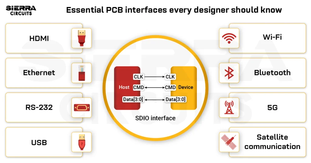
The choice of the PCB interface plays a critical role in enabling efficient protocol layering, minimizing crosstalk, and supporting advanced techniques like differential signaling and adaptive equalization.
As a PCB designer, understanding circuit board interfaces will help you choose and implement the right one. This ensures minimal signal loss, compatibility between components, and prevents system failures or board respins.
Highlights:
- PCB interfaces are electrical and logical connections that enable data, power, and control signal transmission through protocols like SPI, I2C, Bluetooth, or Wi-Fi.
- Circuit board interfaces are categorized into wired (e.g., UART, I2C, PCIe) and wireless (e.g., Bluetooth, Wi-Fi, LoRa).
- The choice of interface depends on factors like data transfer speed, communication distance, system complexity, power consumption, and environmental conditions.
In this blog, you’ll learn about wired and wireless PCB interfaces and their roles in enabling communication between components. Each interface is briefly explained, followed by a table highlighting its key characteristics, such as communication type, speed, distance, typical applications, and pros and cons.
What are PCB interfaces?
Printed board interfaces are the electrical and logical connections that enable communication between the board and other components or devices. They define how data, power, or control signals are transmitted using specific protocols or standards, such as SPI, I2C, Bluetooth, or Wi-Fi.
An interface isn’t the same as a PCB connector. A connector is the physical part (like a port or plug) that connects the board to external devices. In contrast, an interface is the entire system that works over that physical link, including the signal lines and the protocols.
Download our eBook to learn more about PCB connectors.
Connector Design Guide
5 Chapters - 32 Pages - 50 Minute ReadWhat's Inside:
- Basics
- Terminology
- Selection and layout rules
- Testing
- Application-specific PCB connectors
Download Now
What are the different types of circuit board interfaces?
PCB interfaces are categorized based on how they connect and communicate with other devices or components.
They can be broadly divided into two types:
- Wired interfaces (like UART, I2C, or PCIe) use physical connections, such as cables or traces, to transmit data, power, or control signals.
- Wireless interfaces (like Bluetooth, Wi-Fi, or LoRa) transmit data without physical connections, using radio waves or other wireless technologies. These are ideal for remote communication or applications where wiring is impractical.
The choice of the interface depends on the signal speed, distance, complexity, and power requirements.
19 wired PCB interfaces every designer should know
1. Universal asynchronous receiver/transmitter (UART)
UART is a simple asynchronous serial communication protocol that transmits data one bit at a time.

Unlike SPI or I2C, UART does not use a clock signal; instead, both devices must agree on a baud rate beforehand.
| Factors | Details |
|---|---|
| Type | Asynchronous serial communication |
| Data lines | Transmit (TX), receive (RX) |
| Communication mode | Full-duplex |
| Number of devices | 2 (point-to-point) |
| Speed | Typically 230 kbps to 460 kbps Baud rates: 9600, 19200, 38400, 57600, 115200, 230400, 460800, 921600, 1000000, 1500000 |
| Distance | Up to 15 meters with RS-232 with lower baud rate; TTL UART is limited to 1–2 meters. |
| Applications | Microcontroller to peripheral communications, GPS, Bluetooth modules |
| Advantages | Simple design, low resource usage |
| Disadvantages | Limited distance, basic error detection (parity only), no built-in error correction |
2. Serial peripheral interface (SPI)
SPI is a widely used interface for high-speed, full-duplex communication between microcontrollers and peripheral ICs like sensors, ADCs, DACs, shift registers, and SRAM. It allows simultaneous data transmission by both master and slave devices.

| Factors | Details |
|---|---|
| Type | Synchronous serial communication |
| Data lines | MOSI, MISO, SCLK, SS |
| Communication mode | Full-duplex |
| Number of devices | Typically 1 master, up to 4–5 slaves (more with extra decoder logic) |
| Speed | Typically, 1 Mbps up to 20 Mbps |
| Distance | Short distance (PCB-level) |
| Applications | Sensors, memory chips, and display modules |
| Advantages | High-speed, full-duplex communication |
| Disadvantages | Short distances, needs multiple chip select lines, no standard error detection |
3. Inter-integrated circuit (I2C)
I2C is a two-wire serial communication protocol that allows multiple devices to share a single communication bus. It supports multiple controllers capable of transmitting and receiving data and commands.

Data is transferred in byte-sized packets, with each target device identified by a unique address.

| Factors | Details |
|---|---|
| Type | Synchronous serial communication (multi-master, multi-slave) |
| Data lines | Data (SDA), clock (SCL) |
| Communication mode | Half-duplex (shared bus) |
| Number of devices | 1 master, up to 127 slave devices |
| Speed | 100 kbps (standard), 400 kbps (fast-mode), 1 Mbps (fast-mode plus), 3.4 Mbps (high-speed mode), 5 Mbps (ultra-fast mode) |
| Distance | Short distance (1-2 meters) |
| Applications | EEPROMs, sensors, and RTC modules |
| Advantages | Only two wires needed, supports multiple devices |
| Disadvantages | Slower than SPI, limited distance |
4. Inter-IC sound (I2S)
I2S is a synchronous serial communication protocol designed specifically for transmitting digital audio data between integrated circuits.

Unlike UART, I2S uses a clock signal to synchronize data transmission and supports separate lines for audio data, word select, and bit clock, making it ideal for high-quality stereo audio streaming.
| Factors | Details |
|---|---|
| Type | Synchronous serial audio interface |
| Data lines | Serial data (SD), serial clock (CK), word select (WS) |
| Communication mode | Half-duplex (stereo audio stream) |
| Number of devices | 1 master, 1 or more slaves |
| Speed | Common sample rates: 44.1 kHz, 48 kHz, 96 kHz, 192 kHz (bit rate depends on resolution) |
| Distance | Short; typically board-level (a few centimeters to tens of centimeters) |
| Applications | Digital audio codecs, DACs, ADCs, sound processors, MP3 players, TVs |
| Advantages | Low jitter in PCB audio signals, low pin count, widely supported in audio ICs |
| Disadvantages | No built-in error correction, limited to audio data, not hot-pluggable |
5. RS-232
RS-232 is a standard for serial communication using single-ended signaling, typically for point-to-point connections over short distances.

| Factors | Details |
|---|---|
| Type | Asynchronous serial communication |
| Data lines | Transmit (TX), receive (RX), ground (GND) |
| Communication mode | Full-duplex (with control signal) |
| Number of devices | 2 |
| Speed | Up to 1 Mbps |
| Distance | Up to 15 meters at lower baud rate; shorter at higher speeds |
| Applications | Industrial equipment, legacy systems, point-of-sale (POS) systems |
| Advantages | Simple, widely supported, good for short-distance communication |
| Disadvantages | Lower speed, short range compared to RS-485, bulky connectors, point-to-point only |
6. RS-485
It is a serial communication standard that uses differential signaling. RS-485 supports multiple devices on a bus over longer distances.

| Factors | Details |
|---|---|
| Type | Asynchronous serial communication |
| Data lines | Differential pairs (D+/D-) |
| Communication mode | Half-duplex (2-wire) or Full-duplex (4-wire) |
| Number of devices | Up to 32 (can be extended with special transceivers) |
| Speed | Up to 10 Mbps for short distances; lower speeds for longer distances |
| Distance | Up to 1200 meters at 100 kbps (speed decreases as distance increases) |
| Applications | Industrial machines, legacy systems, POS systems, and building automation |
| Advantages | Robust against noise, supports long-distance communication, multi-drop capable |
| Disadvantages | Lower data rates compared to modern standards, and the connectors are bulky in some setups |
7. Universal serial bus (USB)
It is a standardized wired protocol used to connect peripherals to computers, supporting plug-and-play and data/power transfer over a four-wire interface.

| Factors | Details |
|---|---|
| Type | Plug-and-play serial communication |
| Data lines | USB 2.0: D+, D-, VBUS, GND USB 3.0: D+, D-, VBUS, GND, SSRX+, SSRX–, SSTX+, SSTX– |
| Communication mode | USB 2.0: Half-duplex (host-controlled, polling) USB 3.0: Dual-simplex |
| Number of devices | Up to 127 devices per host |
| Speed | Up to 40 Gbps (USB4), 5 Gbps+ (USB 3.0), 480 Mbps (USB 2.0), 12 Mbps (USB 1.1), 1.5 Mbps (USB 1.0) |
| Distance | Up to 5 meters typically |
| Applications | Computers, smartphones, peripherals, storage devices |
| Advantages | Widely supported, hot-pluggable, high-speed |
| Disadvantages | Cable length limitations |
8. Ethernet
Ethernet is a widely used networking protocol for wired local area networks (LANs), using twisted-pair cables to transmit data in frames based on the IEEE 802.3 standard.

| Factors | Details |
|---|---|
| Type | Wired network communication |
| Data lines | Twisted pair (e.g., CAT5, CAT6), or fiber optic cables |
| Communication mode | Full-duplex |
| Number of devices | Scalable (depends on switching infrastructure) |
| Speed | 10 Mbps to 400 Gbps (includes copper and fiber standards) |
| Distance | Up to 100 meters on copper; up to several kilometers on fiber |
| Applications | LANs, IoT devices, servers, and industrial automation |
| Advantages | Reliable, high-speed, standardized |
| Disadvantages | Requires infrastructure (cabling, routers, switches) |
9. FireWire (IEEE 1394)
FireWire is a high-speed, serial communication protocol developed by Apple and standardized as IEEE 1394. It supports isochronous and asynchronous data transfer and has been widely used in multimedia applications.

FireWire allows peer-to-peer communication, enabling devices to talk to each other without a host (unlike USB). It also supports hot-swapping and real-time data transfer.

| Factors | Details |
|---|---|
| Type | High-speed serial bus |
| Data lines | Twisted-pair differential pairs for data and strobe; control signals |
| Communication mode | Full-duplex |
| Number of devices | Up to 63 devices on a bus |
| Speed | IEEE 1394a: 100, 200, 400 Mbps; IEEE 1394b: 800, 1600, 3200 Mbps |
| Distance | Up to 4.5 meters per cable (IEEE 1394a); up to 100 meters with optical (IEEE 1394b) |
| Applications | Digital video (DV), audio interfaces, external hard drives, industrial systems |
| Advantages | Peer-to-peer architecture, high throughput, real-time isochronous support |
| Disadvantages | Costlier than USB, gradually phased out in favor of USB and Thunderbolt |
10. Controller area network (CAN)
The CAN communication protocol is a multi-master serial system commonly used in automotive and industrial applications for real-time data exchange over a two-wire bus.

| Factors | Details |
|---|---|
| Type | Multi-master serial communication |
| Data lines | CAN_H, CAN_L (twisted-pair cable) |
| Communication mode | Half-duplex (broadcast-based) |
| Number of devices | Typically up to 112 devices |
| Speed | Up to 1 Mbps (CAN), 5 Mbps (CAN-FD) |
| Distance | Up to 40 meters at max speed; longer at lower speeds |
| Applications | Automotive, robotics, industrial automation |
| Advantages | Robust error handling, reliable in noisy environments, and real-time communication |
| Disadvantages | Limited data rate compared to Ethernet |
11. Low-voltage differential signaling (LVDS)
It is a high-speed, low-power signaling method that uses differential pairs to transmit data with low noise and electromagnetic interference, making it suitable for routing high-speed PCBs.

| Factors | Details |
|---|---|
| Type | High-speed differential signaling |
| Data lines | Differential pairs |
| Communication mode | Full-duplex or simplex (depending on design) |
| Number of devices | 2 (point-to-point) |
| Speed | Hundreds of Mbps |
| Distance | Several meters (depends on quality) |
| Applications | Displays, high-speed cameras, medical devices, memory |
| Advantages | Low noise, low power, high speed |
| Disadvantages | Requires careful impedance matching, higher cost |
Try Sierra Circuits’ Impedance Calculator to precisely model your high-speed traces and prevent signal distortion in your designs.

12. Peripheral component interconnect express (PCIe)
PCIe is a high-speed serial expansion bus standard that connects internal components like GPUs and SSDs to a motherboard.

| Factors | Details |
|---|---|
| Type | High-speed serial expansion bus |
| Data lines | Differential pairs (lanes) |
| Communication mode | Full-duplex (lane pairs) |
| Number of devices | Typically, 1 root and multiple endpoints |
| Speed | Up to 64 GT/s (PCIe 6.0), 16 GT/s (PCIe 4.0) |
| Distance | Short (inside PCBs) |
| Applications | Graphics cards, SSDs, and network cards |
| Advantages | High throughput, scalable lanes (x1, x4, x16) |
| Disadvantages | PCB complexity, short range only |
13. High-definition multimedia interface (HDMI)
This is a popular digital interface for transmitting uncompressed video and audio data between devices like monitors and media players over a single cable.

| Factors | Details |
|---|---|
| Type | Digital multimedia interface |
| Data lines | Multiple differential pairs (3 or 4 for data), control lines |
| Communication mode | Simplex (one-way: source → display) |
| Number of devices | 1 source to 1 sink (point-to-point) |
| Speed | Bandwidth: up to 48 Gbps (FRL) Effective data rate: up to 42.6 Gbps (after 16b/18b encoding) |
| Distance | 5 to 10 meters at high speeds, up to 15 meters with signal boosters |
| Applications | Televisions, HDMI monitors, projectors, and gaming consoles |
| Advantages | Single cable for video, audio, and control signals |
| Disadvantages | Distance and bandwidth limitations at high resolutions, unidirectional |
14. Serial advanced technology attachment (SATA)
It is a computer bus interface for connecting mass storage devices like hard drives and SSDs using serial signaling for fast data transfer.

| Factors | Details |
|---|---|
| Type | High-speed data transfer for storage devices |
| Data lines | Differential pair |
| Communication mode | Full-duplex |
| Number of devices | 1-to-1 per port |
| Speed | Up to 6 Gbps (SATA III) |
| Distance | Up to 1 meter (typically) |
| Applications | Hard drives, SSDs |
| Advantages | High-speed data transfer for storage, hot-swappable |
| Disadvantages | Short range, power consumption |
15. Secure digital input output (SDIO)
This wired interface type is an extension of the SD card standard that allows peripheral devices to interface with a host via the SD card slot using serial communication.

| Factors | Details |
|---|---|
| Type | Synchronous serial peripheral connection based on the SD card standard |
| Data lines | CLK, CMD, DAT[3:0] |
| Communication mode | Half-duplex |
| Number of devices | Typically 1 host, 1 device (some advanced host controllers support up to 7 devices) |
| Speed | Up to 25 MB/s, Up to 104 Mbps (SDIO 3.0). |
| Distance | Short (within device or peripheral) |
| Applications | Wi-Fi modules, GPS, Bluetooth peripherals |
| Advantages | Compact, low power |
| Disadvantages | Lower speeds than PCIe/USB |
16. Mobile industry processor interface (MIPI)
MIPI defines low-power, high-speed serial interfaces, such as camera serial interface (CSI) and display serial interface (DSI). It is used for connecting cameras and displays to processors in mobile and embedded systems using differential data lanes.


| Factors | Details |
|---|---|
| Type | High-speed interface standards suite (e.g., MIPI CSI, DSI) |
| Data lines | Differential pairs (2–4 lanes per direction, via D-PHY or C-PHY) |
| Communication mode | Simplex (CSI: sensor → processor, DSI: processor → display) or half-duplex (depending on implementation) |
| Number of devices | Point-to-point (1 source to 1 sink) |
| Speed | Up to 6 Gbps (DSI 2.0), 3 Gbps (CSI 2.0) |
| Distance | Short (on-PCB or module-to-SoC) |
| Applications | Smartphones, tablets, embedded cameras, LCD panels |
| Advantages | Standardized for mobile, high-speed, scalable, low-power |
| Disadvantages | Complex design, limited range, sensitive to noise |
17. Pulse width modulation (PWM)
This is a method of transmitting analog signal levels by varying the duty cycle of a digital signal, commonly used for motor control and dimming LEDs.

| Factors | Details |
|---|---|
| Type | Digital pulses |
| Data lines | Single wire (for digital control) |
| Communication mode | Simplex (controller to device) |
| Number of devices | 1 controller to many devices (if shared) |
| Speed | Varies (frequency can range from 1 Hz to several MHz) |
| Distance | Short (dependent on the device control) |
| Applications | Motor speed control, LED dimming, audio signal modulation |
| Advantages | Energy-efficient, simple design |
| Disadvantages | Switching noise and electromagnetic interference if not properly filtered. Non-linear behavior in some applications. |
18. Double data rate (DDR)
DDR memory is a high-speed synchronous interface used to connect dynamic random-access memory (DRAM) to a memory controller, commonly found in processors, system on a chip (SoC), and field-programmable gate arrays (FPGAs). It transfers data on both the rising and falling edges of the clock signal, effectively doubling the data rate compared to single data rate (SDR) memory.

DDR operates with strict timing and signal integrity requirements, and its interface includes multiple signal types for command, address, control, and high-speed data transfer.

| Factors | Details |
|---|---|
| Type | Synchronous parallel memory interface |
| Data lines | DQ (data lines), DQS (data strobe), address, command, and control lines |
| Communication mode | Half-duplex (separate read and write operations, not simultaneous) |
| Number of devices | 1 or more DRAM devices per channel (with or without ranks) |
| Speed | DDR1: up to 400 MT/s, DDR2: up to 800 MT/s, DDR3: up to 2133 MT/s, DDR4: up to 3200 MT/s, DDR5: up to 8400+ MT/s |
| Clocking | Double data rate (transfers data on both clock edges); external differential clock |
| Distance | Very short – typically PCB trace length of a few inches (board-level only) |
| Applications | PCs, laptops, smartphones, FPGAs, embedded systems, graphics cards |
| Advantages | High bandwidth, widely supported, standardized |
| Disadvantages | Complex routing, tight timing margins, require impedance control and termination |
Try Sierra Circuits’ Trace Width, Current Capacity, and Temperature Rise Calculator to accurately compute the line width and spacing for safe operation.
19. Embedded multimedia card (eMMC)
eMMC is a non-volatile storage interface based on the multimedia card (MMC) standard, commonly used in smartphones, tablets, and embedded systems. It combines a flash memory device and a controller in a single BGA package, simplifying storage integration in hardware designs.

Unlike removable SD cards, eMMC is soldered directly onto the PCB and provides a managed NAND flash interface with wear leveling, bad block management, and error correction handled internally.
| Factors | Details |
|---|---|
| Type | Embedded flash memory interface (based on MMC standard) |
| Data lines | 1-bit, 4-bit, or 8-bit parallel data bus, clock, command, reset, and optionally strobe signals |
| Communication mode | Half-duplex (host initiates all transactions) |
| Number of devices | Single eMMC device per controller (not meant for sharing) |
| Speed | Up to 400 MB/s (HS400 mode) |
| Clocking | Synchronous clocked interface; supports dual data rate in HS200/HS400 |
| Distance | Very short (embedded device; traces within the PCB) |
| Applications | Smartphones, tablets, embedded systems, IoT devices, automobiles |
| Advantages | Compact, cost-effective, integrates controller and NAND flash, standard boot and storage functions |
| Disadvantages | Not removable, limited upgrade options, lower performance than UFS |
Download our eBook to learn about design for assembly.

Design for Assembly Handbook
6 Chapters - 50 Pages - 70 Minute ReadWhat's Inside:
- Recommended layout for components
- Common PCB assembly defects
- Factors that impact the cost of the PCB assembly, including:
- Component packages
- Board assembly volumes
Download Now
9 types of wireless PCB interfaces
1. Wireless fidelity (Wi-Fi)
This is a wireless networking protocol based on IEEE 802.11 standards, enabling devices to connect to local area networks and the internet using radio waves.

| Factors | Details |
|---|---|
| Type | Wireless communication via radio waves |
| Data lines | Radio frequency (2.4 GHz and 5 GHz, 6 GHz for Wi-Fi 6E) |
| Communication mode | Half-duplex (shared medium, collision avoidance) |
| Number of devices | Typically up to 250 devices per access point |
| Speed | Up to 9.6 Gbps (Wi-Fi 6) |
| Distance | Up to 100 meters (depending on the environment) |
| Applications | Internet access, IoT devices, home networks |
| Advantages | High-speed, convenient, widely available |
| Disadvantages | Signal interference, security concerns |
To learn how to design RF boards, see RF PCB design: 9 factors to consider.
2. Bluetooth
A Bluetooth interface enables wireless communication by forming a short-range network called a piconet, which includes one master device and multiple slave devices that communicate directly with the master.

Several interconnected piconets can form a larger structure known as a scatternet, where certain devices, called bridge nodes, participate in more than one piconet to facilitate communication between them.
| Factors | Details |
|---|---|
| Type | Short-range wireless communication |
| Data lines | Radio frequency (2.4 GHz ISM band) |
| Communication mode | Half-duplex (TDM-based) |
| Number of devices | 1 master, up to 7 active slaves |
| Speed | Up to 3 Mbps (Bluetooth 2.0 + EDR), 1 Mbps (Bluetooth 4.0 LE), 2 Mbps (Bluetooth 5.0 LE) |
| Distance | Typically up to 10 meters (classic Bluetooth), up to 100 meters (Bluetooth 5.0 LE) |
| Applications | Wireless audio, IoT devices, mobile peripherals |
| Advantages | Low power consumption, easy pairing |
| Disadvantages | Limited range, interference with other devices |
Sierra Circuits manufactures high-precision RF and microwave PCBs with tightly controlled impedance and low signal loss. See RF and microwave PCB capabilities to learn more.
3. ZigBee (802.15.4)
In ZigBee communication, devices form a mesh network where data is transmitted between nodes using short-range, low-power wireless signals. The network includes the following devices and nodes.
- Coordinator- Central device that initiates, manages, and secures the network. Only one exists per network.
- Routers (nodes) – Forward data between devices, extending network range.
- End devices- Send and receive data via a parent router.
 mesh network")
Messages can hop through multiple nodes to reach their destination, enabling reliable communication even over longer distances or around obstacles.
| Factors | Details |
|---|---|
| Type | Low-power, low-data-rate wireless communication |
| Data lines | Radio frequency (2.4 GHz ISM band, 868 MHz EU, 915 MHz US bands) |
| Communication mode | Half-duplex (CSMA/CA or mesh routing) |
| Number of devices | Up to 65,000+ |
| Speed | Up to 250 kbps |
| Distance | Up to 100 meters (with mesh networking) |
| Applications | Home automation, industrial control, health care |
| Advantages | Low power, simple mesh networking |
| Disadvantages | Low data rate, limited range |
4. Long range (LoRa)
As the name suggests, LoRa is a long-range, low-power, wireless communication protocol used for IoT networks, especially where wide coverage and low data rates are needed.

LoRa end nodes use sensors to collect data and wirelessly transmit it to nearby LoRaWAN gateways, which forward it to the cloud. Multiple gateways within range can receive the same signal, forming a star-on-star topology that enhances network reliability and coverage.
| Factors | Details |
|---|---|
| Type | Low-power, long-range wireless communication |
| Data lines | Radio frequency (sub-GHz bands) |
| Communication mode | Half-duplex (LoRaWAN class-dependent) |
| Number of devices | Thousands of nodes per gateway (depends on traffic and region regulations) |
| Speed | Up to 50 kbps |
| Distance | Up to 15 km (in rural areas) |
| Applications | Smart cities, agriculture, industrial IoT |
| Advantages | Long range, low power consumption |
| Disadvantages | Low data rates, requires dedicated gateways |
5. Near field communication (NFC)
NFC is a short-range wireless communication protocol enabling data exchange over distances of a few centimeters, commonly used for contactless payments.

| Factors | Details |
|---|---|
| Type | Short-range wireless communication |
| Data lines | Radio frequency (13.56 MHz) |
| Communication mode | Half-duplex (alternating communication) |
| Number of devices | 2 |
| Speed | Up to 424 kbps |
| Distance | Up to 10 cm |
| Applications | Contactless payments, access control, pairing devices |
| Advantages | Very fast setup, secure communication |
| Disadvantages | Very short range, limited speed |
6. 5th generation (5G)
This fifth-generation cellular network standard offers ultra-fast data rates, low latency, and massive device connectivity for mobile and IoT applications.

| Factors | Details |
|---|---|
| Type | Next-generation mobile network |
| Data lines | Radio frequency (sub-6 GHz and mmWave bands) |
| Communication mode | Full-duplex (TDD/FDD depending on band) |
| Number of devices | Up to 1 million per sq. km (theoretical in dense IoT deployment) |
| Speed | Up to 10 Gbps |
| Distance | Shorter ranges for mmWave, longer for Sub-6 GHz |
| Applications | Smartphones, IoT, smart cities, autonomous vehicles |
| Advantages | Ultra-high speed, low latency, longer distance |
| Disadvantages | High infrastructure cost, limited rural coverage |
To learn more about designing 5G boards, see how to design PCBs for 5G wireless applications.
7. Satellite communication
This wireless technology enables long-distance communication using satellites to transmit and receive signals between ground stations and devices globally.
The IEEE categorizes satellite communication frequencies into the C, X, Ku, and Ka bands, as outlined below.
| Band | IEEE designation | Uplink (GHz) | Downlink (GHz) | Applications |
|---|---|---|---|---|
| C | 4–8 GHz | 5.8–6.725 | 3.4–4.2 | Fixed satellite services (FSS), TV broadcast, enterprise networks |
| X | 8–12 GHz | 7.9–8.4 | 7.25–7.75 | Military and government communications |
| Ku | 12–18 GHz | 14.0–14.5 | 10.7–12.75 | VSAT, direct-to-home TV (DTH), commercial broadcasting |
| Ka | 26.5–40 GHz | 27.5–31.0 | 18.3–18.8 or 19.7 to 20.2 | High-throughput satellites (HTS), broadband internet |
The exact frequency ranges can vary by region and application, and are often classified to prevent interference or ensure security.

| Factors | Details |
|---|---|
| Type | Long-distance wireless communication via satellites |
| Data lines | Radio frequency (multiple bands: C, Ku, Ka) |
| Communication mode | Full-duplex or Half-duplex (depends on the system) |
| Number of devices | Thousands to millions |
| Speed | Up to 100 Mbps or higher (modern systems) |
| Distance | Thousands of kilometers |
| Applications | Remote internet, navigation (GPS), TV broadcasting |
| Advantages | Global coverage, reliable in remote areas |
| Disadvantages | High latency, expensive equipment |
8. Radio frequency identification (RFID)
It is a wireless identification system that uses electromagnetic fields to read and write data from tags attached to objects, often used in tracking and access control.

| Factors | Details |
|---|---|
| Type | Short-range identification and tracking |
| Data lines | Radio frequency (125 kHz, 13.56 MHz, UHF) |
| Communication mode | Half-duplex (reader initiates, tag responds) |
| Number of devices | Hundreds to thousands (depending on reader type and tag type) |
| Data rate | Depends on the system; typically low to moderate |
| Distance | Few centimeters to several meters (UHF RFID) |
| Applications | Inventory tracking, access control, and logistics |
| Advantages | No line-of-sight needed, fast scanning |
| Disadvantages | Susceptible to interference, security risks |
9. Z-Wave
Z-Wave is a low-power, wireless communication protocol designed for smart home and automation systems, commonly integrated into PCBs to enable device connectivity. It operates on a mesh network topology, allowing devices to relay messages to extend range and reliability.

Unlike UART, Z-Wave is not a hardware-level interface but a wireless protocol layer that typically runs on a SoC or module, which communicates with a host microcontroller via serial interfaces like UART or SPI.
| Factors | Details |
|---|---|
| Type | Wireless mesh network communication interface |
| Data lines | Radio frequency (sub-GHz bands: 868.42 MHz EU, 908.42 MHz US) |
| Communication mode | Half-duplex (bidirectional, but not simultaneous) |
| Number of devices | Supports up to 232 nodes in a mesh network |
| Speed | 9.6 kbps to 100 kbps, depending on the Z-Wave version |
| Clocking | Asynchronous, based on internal device timing |
| Distance | 30–100 meters indoors, longer with mesh relay between nodes |
| Applications | Smart home devices, lighting control, door locks, thermostats, sensors |
| Advantages | Low power, interoperable, robust mesh networking, operates in the sub-GHz band (less interference) |
| Disadvantages | Lower data rate, limited bandwidth, requires Z-Wave-certified hardware |
Key takeaways:
- A PCB interface defines the methods for data exchange over physical connections.
- Connectors are the physical hardware links, while printed circuit board interfaces define the communication protocols that operate over those connections.
- Common wired interfaces include UART, SPI, I2C, I2S, RS-232, RS-485, USB, Ethernet, FireWire, CAN, LVDS, and PCIe.
- Key wireless interfaces comprise Bluetooth, Wi-Fi, LoRa, ZigBee, and NFC, used for cable-free communication between devices.
- Each interface has unique properties: data lines, communication mode, speed, distance, applications, advantages, and disadvantages.
- Understanding interface specifics helps PCB designers optimize board layout, enhance signal integrity, ensure electrical and protocol compatibility between components, and improve overall system reliability.
Understanding PCB interfaces is essential for designing robust electronic systems. By selecting and implementing appropriate interfaces, electrical engineers can ensure low-loss communication between components in modern devices.
Have questions about printed circuit board interfaces? Post your queries on SierraConnect. Our PCB experts will answer them.

About Pooja Mitra : Pooja Mitra is an electronics and communication engineer. With an experience of over three years in the PCB industry, she creates industry-focused articles that help electrical and PCB layout engineers.


Wow, I don’t remember seeing such a comprehensive compilation anywhere before. Haven’t read it yet, and given it’s probably intended as a quick reference on whichever interface you happen to be considering at a particular moment (but then delving deeper into it somewhere else), I’ll just keep it bookmarked. I am hugely impressed with your work on this topic. SierraConnect sure is a great place to be a part of.
Thanks!