


Contents
A rigid-flex video processor board is a high-performance and viable solution for embedded video and image processing. The fabrication involves a series of interesting processes and has some unique specifications.
Sierra Circuits designed a rigid-flex high-speed digital video board that enables high-quality video processing. In this case study, we will discuss the specifications and critical design constraints concerning this board.
Specifications of this rigid-flex video board
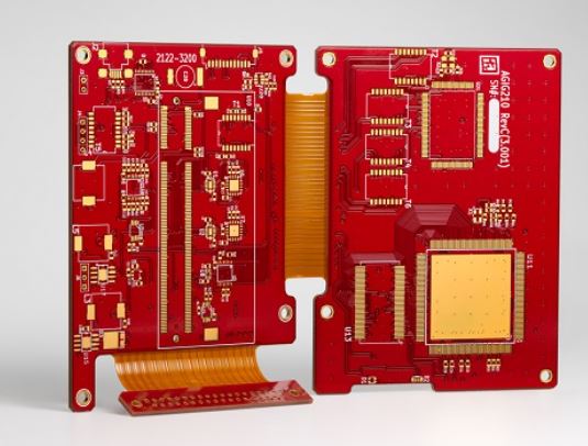
- It is a 10-layer board, i.e. an 8-layered rigid-flex connected to a 2 -layered rigid-flex.
- The size of the larger section is 27 mm x 26 mm (1.06″ x 1.02″), whereas the smaller section is 12 mm x 16 mm (0.47″ x 0.62″).
- The operating frequency is set as 700 MHz.
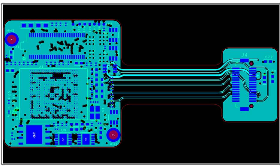
- Consists of FPGA of 325 pins with 0.5 mm pitch. It is mounted on the PCB and can be configured after manufacturing the circuit board. FPGA is reconfigurable as it contains an array of programmable logic blocks.
- The board required controlled impedance traces – 100 Ohm differential and 50 Ohm single-ended. The controlled impedance is the characteristic impedance of a transmission line formed by PCB traces and its associated reference planes. For high-frequency signals, it helps to solve signal integrity problems.

- The board uses an SRAM of 40 MHz and NAND flash of 25 MHz with TSSOP packaging.
- Here, fine pitch with 0.5 mm packaging and via in pad design is implemented. In a fine pitch board, there will be a significant amount of components per square inch. The via-in-pad technology involves the via placement on the copper pad of a surface-mounted component and plated with copper (VIPPO). It ensures a smaller form factor and thus makes the board compact.
Critical constraints and design approach
Anil. S. Raiker, the PCB design head at Sierra Circuits, talked about the design constraints and said, “Firstly, the form factor of this board is very small, almost 1″ x 1” (25.4 mm x 25.4 mm). The second thing is, because of the high density of components and BGA, we have to take care of the via-in-pad design for the BGA. Via-in-pad is implemented to meet drill-to-copper challenges.” He further said that routing 0.5 mm FPGA and BGA packaging was quite difficult as well.
According to Anil, it was tough to place the components as the component density was very high. It was done on the basis of the shortest routing length. He mentioned, “The distance between the source signal and the destination signal is kept as large as possible. The SRAM and NAND Flash are placed on the same board with a minimal form factor. Hence, it requires dense routing with the length matching.”
Applications of the rigid-flex video board
Medical imaging
Medical imaging is required for clinical analysis of a human body or a particular part of a body. Medical flex PCBs are implemented in X-ray, ultrasonography, medical resonance imaging (MRI), endoscopy, computerized tomography scan (CT scan), and many more.

Road traffic monitoring
The stationary video acquisition cameras obtain the optimal view of the road, the vehicles, and the details of people passing by. It comprises of few spatial, and temporal video sequences in a simple way.

Automatic vehicle guidance
It is essential in different abstraction levels to localize the vehicle with respect to the environment. Here it is crucial to examine the dynamic changes in the surroundings.
Automatic optical inspection (AOI):
AOI is a requisite technique that is used to analyze standard and complex PCBs. It verifies the quality of the board by detecting defects if any.

Sierra Circuits’ design team understands the requirements of a rigid-flex board and has an expansive experience in PCB design. The design and the DFM team seamlessly interact with each other and evaluate various routing requirements for a particular design. Our goal is to deliver the desired boards with high performance and quality. Download our design guide to learn about bend radius calculation, controlled impedance for flex, and other important design techniques.

To understand the significance of IPC design guidelines, read our blog IPC-2223 standards and design violations for rigid-flex boards

About Poulomi Ghosh : Poulomi is a microwave engineer specializing in EMI, EMC, RF, and high-speed electronics. As a senior technical writer at Sierra Circuits, she creates advanced engineering articles and webinars for hardware engineers and PCB designers.


