Contents
If we want to design and produce something, we definitely would require the help of a computer and manufacturing machines. A concept called CAM is used to communicate the instructions to the machines.
Introduction to CAM
Computer-aided manufacturing is the use of software and computer-controlled machinery to automate a manufacturing process. Before we get on to the manufacturing process of a PCB, the manufacturers receive the designer’s files in different formats.
These files define the concept of the required PCB. Now, a question might arise in our minds. What information would these files carry? These files contain the information about the board layers needed to fabricate the PCB like IPC netlist, copper artwork, solder mask artwork, drill files, fabrication drawings, etc. One of the prime advantages of the CAM system is its high degree of precision.
What is CAM software responsible for?
The CAM software performs the following tasks once the design files are received from PCB designers:
- Recognizes the format of the artwork layers, drilling data, IPC Netlist, etc.
- Translates the electronic data into images to view, measure, check, and edit the data.
- Verifies layer order sequence.
- Performs design rule checks, and compares the IPC netlists with the imported data.
- Configures nesting of parts on the production panel for the best orientation of the part to maximize machining material utilization and machine efficiency.
- Creates tools for copper, solder masks, silkscreen artwork, drill programs, routing programs, and electrical test programs necessary for manufacturing a PCB from the design. For more, read our post on 6 DFM issues.

What are the components required for a CAM system to function?
Since the age of the Industrial Revolution, the manufacturing process has undergone many changes. The introduction of computer-aided manufacturing is one of those most dramatic changes.
A CAM system requires three components for it to function; they are:
- Software: Instructs a Juki Pick-and-Place Assembly Machine on how to make any product by generating toolpaths.
- Machinery: Transforms the raw materials into a finished product.
- Post Processing: Converts tool paths into a language that machines can understand.
These three modules perform together to form a CAM system. Before we talk further about CAM, it is vital to know about CAD and understand the difference between CAM and CAD.
Difference between CAM and CAD
Computer-aided manufacturing is associated with computer-aided design (CAD) systems. CAD focuses on the design of a product or a part of the product. How is it supposed to look, how should it function? CAM focuses on how to make it.
Every engineering process commences in the world of CAD. Engineers can make either a 2D or 3D drawing. Hence, CAD design is called a model and contains a set of physical properties that will be used by a CAM system.
When CAD completes its design, it’s then fed into CAM. When your CAD model is brought into CAM, the product begins setting up the model for machining. Transforming raw materials into the desired shape by performing actions like cutting, drilling, or boring is called machining.
Introduction to G code
We know that the CAD software prepares the model for machining. But, there should be a language to instruct the machines. A language called G-code is used to instruct the machines. The G-code contains the instructions that control various parameters like the speed and feed rate of a machine.
An example looks like this:
G01 X1 Y1 F20 T01 S500
This breaks down from left to right as:
- G01: Indicates linear movement based on the coordinates X1 and Y1.
- F20: Sets the distance the machine should travel in one spindle revolution. (Feed rate)
- T01: Instructs the machine in the tool section. The given instruction selects the tool 1.
- S500: This command sets the spindle speed.
What are these machines? And how do they work with G-Code?
CNC machining is the process of programming the CNC machine to perform specific actions. Earlier, in the past, machinists used to operate the manufacturing centers manually. Now, human intervention is only required to load a program, insert raw material, and then unload a finished product.
Schematic diagram of data output from PCB CAM and its explanation
CAM or Computer Aided Manufacturing software supports both prototyping and line production. The primary aim is numerically controlled drilling and component insertion. In numerical control, a computer-based controller translates a sequential list of codes into instructions that can be understood by the machine tools.
The whole concept is summarized as computer-assisted manufacturing. The design will be put into production after the fulfillment of all the design parameters.
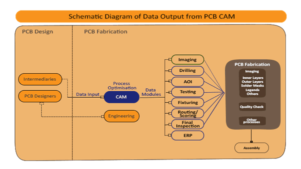
CAM/CAD software plays a vital role in PCB manufacturing as it provides the designer with more control over the production process. CAM is implemented for precise PCB manufacturing, while CAD is for designing a PCB. From imaging to final inspection, CAM files drive the PCBs through the manufacturing process.

Design for Manufacturing Handbook
11 Chapters - 96 Pages - 90 Minute ReadWhat's Inside:
- Annular rings: avoid drill breakouts
- Vias: optimize your design
- Trace width and space: follow the best practices
- Solder mask and silkscreen: get the must-knows
Download Now
About Milan Yogendrappa : Milan Y is an electronics and communication engineer with over 6 years of experience in developing and editing technical articles related to PCB design, manufacturing, and assembly. He is currently the editor-in-chief at Sierra Circuits.