Contents
Our first HDI webinar is entitled ”An HDI Class with Sierra Circuits.” We recorded it at our Bangalore office in June 2019 with Vadiraj Kulkarni, Senior PCB Consultant. As the name suggests, this HDI webinar is actually a class. During the recording, we had our content writers Taisha, Rahul and Pankaj sit in the room with Vadiraj, as he was going through the slides. The goal is to make this online event interactive. Your feedback is more than welcome!
https://protoexpress.wistia.com/medias/mngxbixa9r#
Lucy: Thank you for joining our HDI class with Sierra Circuits. I’m with Vadiraj Kulkarni, he is our senior PCB Consultant at our Bangalore office, and he’s going to present this HDI webinar.
Vadiraj Kulkarni: Hi, I am Vadiraj Kulkarni. Welcome to the webinar on HDI technologies and I have more than 25 years of experience in manufacturing of the printed circuit boards. So in today’s topic, we are going to define what is meant by HDI, and what are the benefits of HDI compared to the traditional modes, than signal integrity, disciplines, then what type of technology we are adopting for HDI boards, then advantage of this microvia interconnections, then aspect ratio, the cost factor. Then BGA panel strategy; how to rope the places whenever there is a dense a device is there. Like BGA devices are there. Then we’ll study the standard buildups then als we’ll look into some of the pictorial presentation of the HDI PCBs.
Vadiraj Kulkarni: So what is meant by HDI?
So it’s nothing but higher wiring density board right? So when you compare it to conventional PCBs, so here the density is very high in terms of line and space so you can accommodate more places into that and more interconnections then you can bring down the board thickness. Thereby it reduces the aspect ratio. If we consider 1 by 1 when the lines and spaces are less than 4 mil, we term that as HDI. If the wires are less than 150 microns, then the capture pad of this is less than 400 microns so it is termed as HDI. The capture pad means when if the laser is going to hit so the top panel, that is called as capture pad. It is less than 400 microns then higher connection pad densities so more than 20 pads per square centimeter then 120-160 average pins per square inch.
Lucy: Whenever it’s HDI, does it always imply that you’re going to trace with laser?
Vadiraj Kulkarni: No need.
Lucy: It can also be mechanical?
Vadiraj Kulkarni: It can be mechanical also.
It can be mechanical also because if it is only very fine lines hardware smaller wires are also considered as HDI. Having microvias reduces your aspect ratio thereby the reliability of the board gets increased.
Pankaj: Is it viable to have between 50 microvias or it has to be greater than 100?
Vadiraj Kulkarni: No, it can be 50 also there are different methods to achieve that. Not by traditional method there are some editing process are there simulative processes are there thereby they achieve the internally you want like 50 microns, that is 2 mils, right? You can achieve that.
Vadiraj Kulkarni: This density, how the factor of this density is calculated? So there is a formula for that. Wd is equal to beta into square root of Cd into Cc.
Where Cd is parts per square inch and Cc is the average leads per part. Beta is the one which is a factor for calculating the density so they’re normally 2.5 for analog and discrete regions and 3 for analog and digital regions.
Pankaj: How do you separate the analog and digital regions?
Vadiraj Kulkarni: See what is analog region? So analog is a signal which is continuous both in terms of time and amplitude. It is continuous in terms and amplitude whereas discrete means one of the factor is not there. That means if the signal is discrete both in time and amplitude that is called digital. But if it is discrete in only one term time then we term it as a discrete only because of discrete region. We do not call as a digital region. So if it is discrete both in time and time and amplitude then it becomes digital. We can have a different suggestion for that because it is a big subject actually.
So then we come to what are the benefits of opting for HDI? So better electrical performance and signal integrity.
Lucy: Why?
Vadiraj Kulkarni: Better electrical performance means what happens when you introduce microvias you have lot of interconnections so your traces become shorter. It need not go on a lengthy this thing so the traces become short thereby the electrical performance increases because there is a less inductance and capacitance gets reduces on that so that is were and also because of these smaller wires, you don’t have these stubs. Normally in a regular interconnections what happens? Even though your traces, like your controlled impedance traces are there normally there is a mismatch of impedance between the interconnection and the trace because when we calculate impedances we calculate only on the topography of the traces but we never calculate the interconnection that also acts as a trace only. From the top to the bottom that acts as a trace.
In normal places what happens if you are drawing a connection from layer 2 or layer 3 and there is no connection from say 3 to 10 then that area acts as a stump. So that gives you lot of effect of this capacitance and thereby EMI effect will be more. Electromagnetic interference then there is one more factor called RFI – radio frequency interferences. They act on the traces that’s why it is always better to go for HDI for the increases in electrical performances.
Then noise, crosstalk and lower EMI/RFI they are the characteristics of the signal actually. Characteristics of the signal so if you consider HDI how these characteristics improve? We can study that if you say HDI, one of the HDI features short interconnected lengths if you say short interconnect lengths it means signal quality improves crosstalk improves. These are the two qualities from that. And if you say low dielectric constant because we are selecting low dielectric constant for the low loss materials for high speed transmission of the lines so the low dielectric means again the signal quality improves and also crosstalk improves.
Smaller vias or smaller features so signal quality improves there then wiring impact gives you switching noises. Normally switching noises come out of not only switching noises and… switching noises come out from the ground plates. Whatever the ground plates are there in the particular stack-up you get the noise level from there so if you use the via impacts you reduce the switching noises and fine lines and thin dielectric reduces the crosstalk as well as switching noises and also EMI impact. Support for fine pitch components there is a switching noise less and EMI effect will be lesser. So these are the HDI features which I describe which will affect signal integrity, crosstalk and switching noise or EMI. So then there is a cost optimization how cost optimization is because the bill of material becomes lesser. In a normal say 18 layer board what happens? The bill of material required is very high there right? You require around 9 crores right? Then pre tax on all those things. So that bill should get reduced if it get reduces to say 8 layers, you are almost reducing by 30% of your BMI bill of materials.
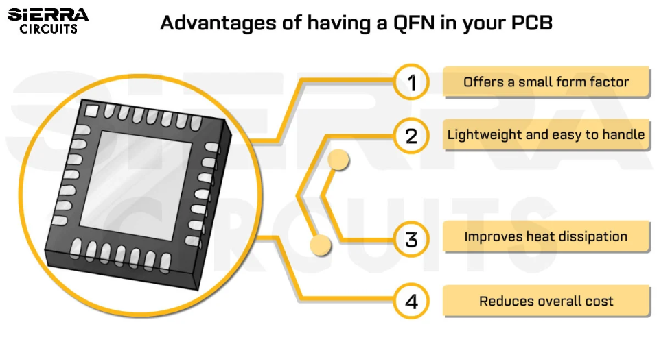
Then reduced design time means what happens when we create lot of microvias, okay for that layout designer to route it becomes easy so he has many interconnections so that he can go to the nearest one. More reliable designs because more reliable means performance wise. It will be more then complex and dense devices. Nowadays the critical BGS like .4mm BGA having more than 300 to 400 inputs and outputs so the tracing becomes very complicated. Thereby using these technologies we can trace, send out those traces wherever it is required because it is very difficult to trace between the two tracts so we can go to the next layer and get connected. Then compact we know the compact the main purpose of this is is compact PCBs right? To reduce the size because we need to produce this PCB to the compactor of the device whatever the electronic is it is there so that compactor we need to look into that so this centurion technology gives you the advantage of reducing the sizes reducing the miniaturization of the PCBs.
I think just now I explained the same thing. Signal integrity discipline so in this what is the discipline. First is the selection of right material. So when we say right material it means for what? For the high transmissions the high transmit signals. High transmission signals means where the loss factor should be minimum then HDI provides.
Lucy: What types of materials do you usually use for HDI?
Vadiraj Kulkarni: HDI we normally use higher Tg materials like ranges from 180-200 then the low Dk values around 3.14 or like that as a dielectric constant and also if you want to say the material in terms of FR4 is a better material and also Megtron series of materials. Megtron C series materials then some Nelco series materials are there.
Then HDI provides significant performance than non HDI because of the stray capacitance and the inductance which I have explained just now.
The above factors will result in higher speed signal transitions, faster rise/fall times and higher clock rates. The transmission speed so the gain factor are coming down and reaching in time because of when you use HDI and all you can achieve those results.
So what are the technologies adapted for HDI? We use blind vias, microvias, buried vias. So I’ve shown in the picture like through-hole, blind, microvia this is the stacked one.
Usually how do we nomenclature this stack-up factors? So suppose it’s an 8-layer board so if I write like 2 plus 4 plus 2, that 2 on the either side represents the number of microvias. Normally the microvias are symmetric in the stack-up so you are having 2 microvias on the top then you should have 2. It’s the sign of good design. It’s the sign of a good design always it should be symmetric. But it is not mandatory also.

Vadiraj Kulkarni: Here we have three lamination cycles. This varied structure is one lamination cycle and along with this, this microvia gets drilled. Then for this microvia, there is one more lamination and for this one more lamination. So the cost factors if you select one press, two press, three press means one lamination, two lamination, three lamination cycle. This is all are different combination of the structures for a given 8-layer board.
Wherein which the number of lamination cycle increases, your cost increases.
Rahul: What’s the maximum number of laminations you can have?
Vadiraj Kulkarni: It is preferred to do limit to the two laminations only that’s what the recommendation is there but some three laminations if it compulsory we have to do it. But I’ve seen five laminations also people are doing. So five lamination they are doing. I think some of the top industries they are doing it.
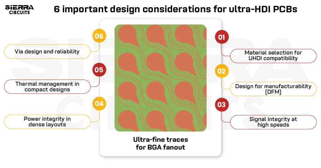
Then BGA fanout, this is more of a layer designer not to the manufacturer actually. So herein which it depends upon the type of device what he is selecting. Not only the device because the device can have 300, 400 things like that but it depends on how many I/Os are acting. If he’s only using 100, 150 I/Os, then it will not be much difficult to route those traces. But when it is used more than 80% of the pins then it becomes very critical for routing those traces so how we connect from… so here in this signal case you can see that the blue colors are connected to the top layer, this the second layer and the third layer this is connected to third layer that’s how this is done.
For this I think we should have… we should interact with the designer more to understand how exactly we can have a plan for like .4mm BGA, .8mm BGA so how if these many connections are there, how tracing is done. How routing is done? I think we can straight up sit with the designer and study these fanouts.
One of the technologies these fanouts can use is like mechanical vias right? We can use to connect those things we can use like this dog bone shaped mechanical vias. Then if you can use these microvias that fanout like this so you get lot of space there right? Even the density of the pad is more see compared to mechanical, density of the pad is more, still you are getting more spacing. Then you can use this via in pad technology.
So using all these three technologies; microvias, then via in pad, then mechanical vias wherever it is required, we can route those traces.
Taisha: What’s the best fanout strategy? Any best practices?
Vadiraj Kulkarni: All these three technologies are used. What people say is that .4mm BGA is the critical one. We use almost all these three technologies there. There is a microvia, there is a via in pad, some mechanical vias are also there. Sometimes it is absent, mechanical vias can be absent. The mechanical vias are predominantly presenting like .8mm BGA and all. But when you go to .4, these mechanical vias almost gets eliminated. It is only microvias then these via in pad.
Now let us see some of the complete buildups complete build-ups. So there we have only shown the picture of that. Here how the stack-up is created you can see here. That is this construction like 3 plus 4B plus 3 so can anybody explain me this one?
Rahul: 3 microvias on either side.
Vadiraj Kulkarn: Yes, 3 microvias on either side. You can see these layout, 4 to 7 there is a buried. So in this construction what he has used is, what is this called?
So the designer started with .51 core, .5mm core then he added prepreg and foil construction done then this buried connection is established, after that again additional prepregs we have added. Then copper foil we have created this third microvia between 3 to 4 and 8 to 7 again addition of prepreg and copper foil. So this is like a sequential right? So sequential buildup 3 sequential buildup. So microvias is nothing but a number of sequential buildups. 3 buildups are there. So the foil, normally they start with very less of a foil, sometimes it depends on the trace speed actually. If the traces are less than 3 mil and all, it’s okay to start with 12 microns, if it less than 3 mil, you have to go with 9 microns. If dual, then some people use 3 microns also, 3 microns start a copper prime base. These prepregs, so these are all high zinc content prepregs here 1080. See one ply, one ply so between the microvias you can use one ply but whenever these types of structures are there it is better to have two plies there.
So this board thickness is around 60 mils. You can calculate that, see you can add up all these, you can add up these three base thickness, this final thickness as written so what I’m doing here we add up all the microns. We add up all that, we get the total board thickness. Now one more is easier, it is very simple 10 buried, one microvia on either side. There is also how many 62 mil board thickness. Here this side is starting with 9 microns. That’s why it depends on the trace width of that particular region.
Then the picture, you can see here, there are some HDI PCBs in the showcase, this is an 8-layer HDI with .4mm BGA. Whenever HDI is said, then the number of layer count comes down only. It is not like that so it is probably if it is the same design the novel case would have been like 14 layer board. Now it has been brought down to the 8 layer board. You can see the thickness how much it is there? Almost 47 mils. 47 mils. So the construction is 2 plus 4 plus 2 and there are stacked microvias L1-L2, L2-L3, L6-L7 and L7-L8 buried between the L3 and L6.
Lucy: And that’s controlled impedance?
Vadiraj Kulkarni: Controlled impedance
Lucy: Whenever you have HDI, do you always have controlled impedance as well?
Vadiraj Kulkarni: Yes. It will be there. It is not like that whenever there is some shorter length places, we need not assign it as a controlled impedance. That is the responsibility of a designer to take care of it, but whenever the length… some places will be length is more and those places will be termed as a controlled impedance places. It depends on that particular trace whether it is a single or a differential so all that there is a strict line. So it depends on the nature of the trace so they assign these controlled impedances.
Here it is a 20-layer board. You can see here blind from both sides via in pad is there for this L1 to L8, L13 to L20. Microvias between L1 and L2, L19 and L20. Blind via, microvia 32 impedance layer traces are there in this single ended differential.

Pankaj: Is it a lot?
Vadiraj Kulkarni: Very lot. Then these are like rigid-flex PCBs. It is like 6 rigid on either side and 2 flex layers with a line width of 4 mils, 62 mils in some medical applications.
These are very high aspect ratio boards, so even after introducing the distinct design aspect ratio like 34 layer ATE boards. These ATE boards can go up to 45 layers also. Why what is this ATE boards means? These are Automatic Test Equipment. We know this IPs are there right? Intellectual properties are particular within them so whenever any company designs those IPs for a specific program and that IPs has to be tested. So to test those design, you need these boards.
It is a special material called S1000-2 aspect ratio is 18:1. So if you want to know more about this please refer our HDI design guide which is available on our website also.

HDI PCB Design Guide
5 Chapters - 52 Pages - 60 Minute ReadWhat's Inside:
- Planning your stack-up and microvia structure
- Choosing the right materials
- Signal integrity and controlled impedance in HDI
- Manufacturing considerations for higher yields
Download Now