


Contents
With the advancement of technology and miniaturization of devices, the heat generated per unit area on a PCB has increased significantly. Components such as ICs generate more heat when running at high speeds. To dissipate this heat away from the PCB we typically use a heat sink. To ensure better connectivity between the IC and the heat sink thermal pads can be used with thermal paste.
They ensure better heat transfer from the component to the heat sink. Better the conductivity of the heat sink paste, better the heat dissipation. In case we don’t apply the thermal paste, the temp of the IC may go higher than its maximum operating temp. This will eventually burn out the IC and the peripheral PCB area and damage the peripheral component. Let us take a look at how thermal pads and thermal paste help in thermal management.
What are thermal pads and thermal paste?
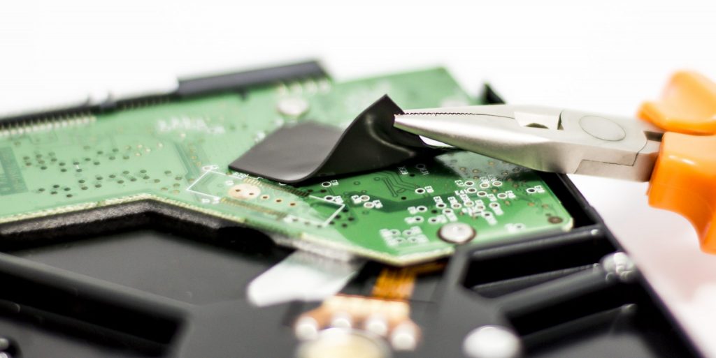
Thermal pad
A thermal pad is a large area of metal that you can solder a device to or on the PCB, or bolt a heat sink onto. These are small pieces of thermally conductive material that transfers heat between objects on a circuit board. Thermal pads are electrically insulating materials that conduct heat such as a combination of ceramics and silicone. They are placed between the component generating heat and the heat sink.

It is also worth noting that thermal relief pads are also called thermal pads which help in the soldering process of a through-hole lead to the board.
Thermal paste
Thermal paste is also called heat sink compound or thermal grease and conducts heat in the same manner as the thermal pad. While thermal paste is made out of similar materials as the thermal pads, it comes in a liquid form that can be manipulated to fit the area that requires the thermal interface material. Thermal paste between the heat-generating component and the heat sink will close any air gaps between the two. When left unfilled, the air gaps would act as thermal insulators hindering heat transfer and dissipation. Filling the air gaps enhances the heat transfer, and dissipation through the heat sink.
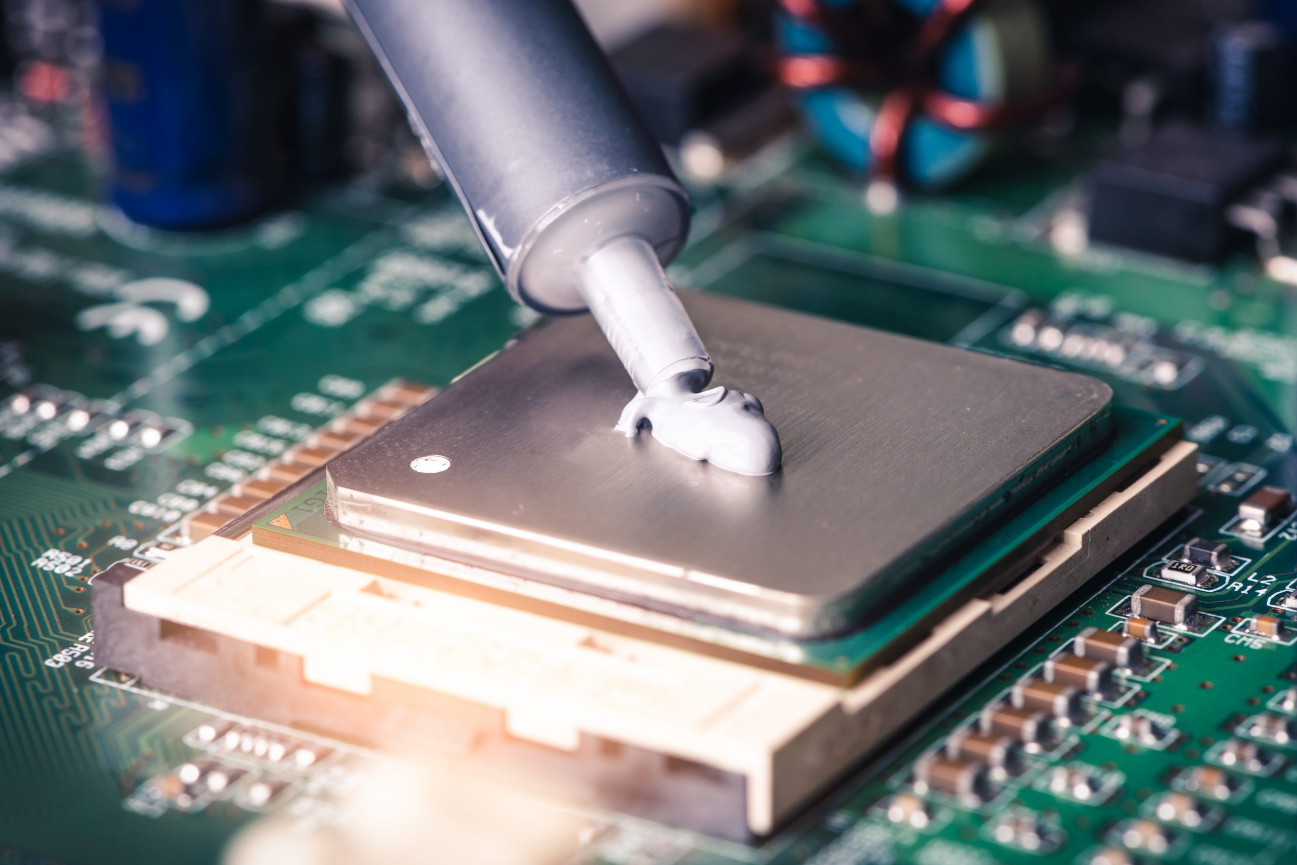
Application of thermal paste
Thermal paste selection
There are several factors to consider when selecting a thermal paste. Given below are the factors to consider while selecting the thermal paste:
| Property | What to consider | Evaluation method |
|---|---|---|
| Thermal Conductivity | Thermal conductivity | Static thermal testing of power electronics assembly |
| Viscosity | Higher viscosity pastes can cause substrate cracking in baseplate-less modules and be difficult to screen print. | Assembly testing, production line qualification |
| Compatibility with customer requirements | Certain industries restrict the use of particular substances (e.g. silicone). | Inspection of paste datasheet |
| Pump-out resiliency | Certain pastes and module types (baseplate) are more susceptible to being “pumped out” from beneath the module. | Power cycling of the module |
| Dry-out resiliency | Certain pastes are more susceptible to drying out over time. | Thermal/environmental cycling |
Carriers and fillers
The carrier material in a thermal paste is typically categorized as silicone or non-silicone type. Generally, manufacturers recommend using silicone-based pastes since they are tried and tested, cost-effective, high performing, and very reliable. When manufacturing facilities need silicone-free pastes, the carrier can be a mix of synthetic fluids. The filler material most thermal pastes are composed of is metal oxide (ZnO, Al2O3) graphite or silver.
Heatsink specification
The surface finish of the heatsink is also a critical part of the thermal interface. Specifications for roughness, unevenness over distance, are to be considered along with the use of a baseplate for the component or module.
Applying to module/component vs applying to heatsink
The order of assembly during the production process will decide if you need to apply the paste to the module/component first or the heatsink. Also to be considered is the mechanical design of the product before application of the thermal paste.
Preparation of paste
Pastes will have to be mixed before application to check for homogenization of the carrier and filler materials. You also need to check if the consistency of the stored thermal paste is a reason for concern. Mixing can be done by manually stirring in its container or using automated mixers as used in automated screen printing. Well-mixed paste should display uniform consistency and color without any standing carrier material. Pastes that require a solvent may need mixing to be done according to manufacturer specifications.
Use of roller
A roller can be used to apply thermal paste directly to the bottom of the module for PCB prototyping and low-volume production. Despite being low cost, this method of application results in inconsistent thicknesses and is messy. The roller ensures a uniform distribution of paste during the application process.
Is thermal paste better than thermal pads?
In the end, the use of a thermal pad or paste depends on the application. The PCB designer and manufacturer will have to carefully assess the board’s needs and select the one that suits them best. In some cases, using a combination of both thermal pad and thermal paste will provide the best results in thermal management.
To get more expert insights on thermal management for PCBs, see PCB heat dissipation techniques by Keven Coates

Checklist for thermal paste usage
In order to know when you require thermal paste in an assembly, follow this checklist:
- The PCB includes processors such as CPUs, GPUs, and MPUs, power regulators, power ICs
- The PCB includes power components such as power amplifiers
- The PCB includes a power supply
- If the PCB has a high component density
- If the thermal profile of the PCB does show thermal hot spots or high-temperature areas
If your board meets any of the criteria mentioned above, then the PCB might need thermal paste to aid other heat transfer devices like thermal pads, heat sinks, and vias. You can use thermal analysis in board design to decide for sure whether you require thermal paste in the PCB.
Also read how to choose PCB materials and laminates for fabrication.
Advantages and disadvantages of thermal pads and thermal paste
Both thermal pads and thermal paste have their own advantages and disadvantages as given below.
Advantages and disadvantages of thermal pads:
- The application of a thermal pad is a relatively clean process and not messy.
- The material is easy to work with and can be cut to precise sizes.
- Thermal pads are available in a wide range of materials allowing for custom applications.
- These are more expensive, and cutting and fitting them will add to your PCB’s manufacturing time.
Advantages and disadvantages of Thermal Paste
- Thermal paste is inexpensive compared to thermal pads.
- Paste has proven to be very reliable in its different applications.
- The paste can be easily applied, fills uneven gaps and surfaces.
- It offers a much thinner interface that provides for enhanced thermal conductivity.
- Thermal paste is messy and can dry out, and it doesn’t have as much mechanical strength as a pad.
- Thermal paste is more durable than thermal pads and is a sturdier option when compared to a thermal pad. This is because thermal paste will hold up better under repeated thermal cycling.
Also, read the advantages of metal core printed circuit boards.
What is a thermal relief pad?
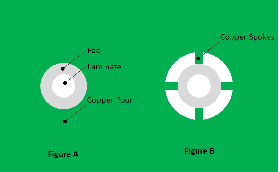
Thermal relief is a technique used by PCB manufacturers to thermally separate soldering pads from large copper areas, to prevent excessive heat transfer from the pads during the soldering process, which would result in delayed melting of the soldering alloy or even no melting at all.
To know more about pad design read our article What is a Pad in PCB Design and Development?
In the figure given above, there are two kinds of pads that are immersed in a copper pour. Figure A shows a conventional pad that is connected to a copper pour in all directions. Figure B shows the pad is connected to the copper pour through four spokes or traces. This is a thermal relief pad.
Even though this technique is a clear requirement from a manufacturing standpoint, designers exercise caution when using it. This is because thermal relief brings about concerns regarding the under-utilization of heat transfer capability of large copper areas. This might lead to localized thermal hot spots at component terminals.
Thermal management of your PCB involves several aspects such as the design of power planes, trace routing, via placement, and thermal relief pads. Mastering these aspects as a designer will ensure a more efficient and reliable PCB design.

Design for Manufacturing Handbook
11 Chapters - 96 Pages - 90 Minute ReadWhat's Inside:
- Annular rings: avoid drill breakouts
- Vias: optimize your design
- Trace width and space: follow the best practices
- Solder mask and silkscreen: get the must-knows
Download Now


