


Contents

On-demand webinar
How Good is My Shield? An Introduction to Transfer Impedance and Shielding Effectiveness
by Karen Burnham
Flex PCBs are used in aerospace, medical devices, consumer electronics, and automotive applications where lightweight, compact, and reliable connections are needed. Their flexibility allows them to fit into tight spaces and complex designs.
These circuit boards can replace traditional wiring harnesses and ribbon connectors in compact designs. They also offer improved resistance to vibration and fewer assembly requirements compared with conventional connections.
In this article, you’ll learn what flex PCBs are, why to choose them, their history, applications, and how they are classified.
Highlights:
- Flex circuit boards provide greater design flexibility for routing circuits through tight spaces and complex three-dimensional shapes.
- Their resistance to vibration makes them suitable for demanding aerospace, automotive, and other harsh-environment applications.
- Flex boards are divided into three classes based on inspection, testing, and performance requirements, with five IPC types based on their construction.
- They are used across aerospace, medical devices, consumer electronics, and automotive applications.
What is a flex PCB?
It is a type of circuit board with very thin substrates and high levels of bendability, tensile strength, and physical flexibility. They can also be molded into complex three-dimensional shapes for use across a diverse range of applications, such as heads-up displays for aerospace piloting, wearable technology, and minuscule devices (e.g., modern hearing aids) for medical care.
The materials used in flex board designs can be just a few microns thick and still be reliably etched. This makes flex PCBs a better choice than rigid boards for applications that require greater flexibility. They can also replace traditional wiring harnesses and ribbon connectors, helping save space and simplify connections.
For example, a flex printed circuit (FPC) can be routed at tough angles within the tight confines of a device such as a satellite, while still sporting a sufficiently high conductor density.
This adaptability is not possible when using ribbon cables. Moreover, flex PCBs unlock many physical design advantages, including:
- 360-degree bendability
- Superior resistance to vibrations and other disruptions within harsh environments
- Support for compact, lightweight design; product weight can be greatly reduced
- Small, flexible cables that take up less space than typical wires
- The ability to be warped or contorted without any associated breakage
On the manufacturing side, flex PCBs are similarly advantageous. They permit better airflow and heat dissipation than many other printed boards. Their modest counts of interconnections and components also mean that their assembly costs are much lower than those for traditional wiring harnesses.
Also, there is less overall susceptibility to assembly errors, since the manufacturing process is streamlined and standardized, without the problematic manual input required for building many of these harnesses.
Flex printed boards are often the best choice for connecting complex electronics internal systems. Flexible circuits are ideal for devices within the aerospace, medical, and consumer technology fields, as they are more versatile and, dare we say, flexible than their rigid alternatives. Thinner, more compact products are an obvious result of flexible circuits as well.
To learn how to design FPCs, download the Flex PCB Design Guide.
Flex PCB Design Guide
10 Chapters - 39 Pages - 45 Minute ReadWhat's Inside:
- Calculating the bend radius
- Annular ring and via specifications
- Build your flex stack-up
- Controlled impedance for flex
- The fab and drawing requirements
Download Now
Why should you choose flex printed boards?
Flex PCBs offer significant mechanical and chemical advantages over conventional ribbon cables in a variety of applications.
A flex circuit can be formed in complex shapes in three dimensions with branches to multiple connectors, which would be impossible to achieve with a ribbon cable.
Moreover, flex circuits can be interfaced with rigid boards without the relatively tall and bulky connectors flat cables require, or in the case of rigid-flex construction, they can be integral with the boards and eliminate external connectors altogether. Furthermore, the conductor density of flex circuits can far exceed that of ribbon cables.
There are some subtle advantages of flex circuits versus conventional ribbon cables beyond the many clear distinctions. One of the materials commonly used for flex circuits, Kapton, has extremely low outgassing in ultra-high-vacuum environments, such as space. Though Kapton-insulated ribbon cables are available, they have a limited number of conductors and cannot be routed at angles in tight confines.
Ribbon cables insulated with Teflon and other plastic materials outgas fluorine or reactive compounds when subjected to high vacuums, which can attack electronics in closed containers if care is not taken to completely vent the gases.
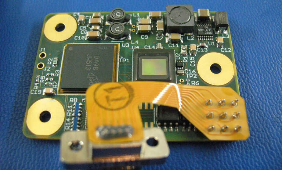


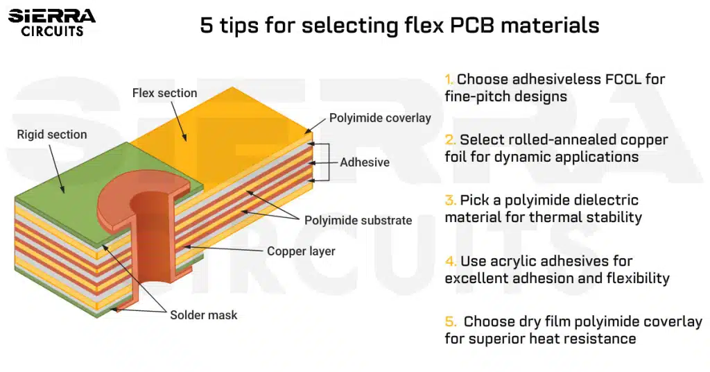
Redesigning a product to use flex rather than rigid PCBs delivers immediate benefits in weight. Customers commonly see weight reductions of up to 75% when compared to traditional designs. This comes from using incredibly thin substrates made of polyester or polyimide material, films that can be as thin as 12-120 microns thick. Conductive material traces are etched on the flex printed board, in as many layers as the PCB design requires. Typically, a coverlay is then applied to protect the layers from moisture, dirt, and damage.
One important use of flex PCB design is the replacement of wiring harnesses and ribbon connectors once used to link together different boards, for example, to connect the engine control unit in an automobile to the dashboard or lighting components. The standardization and economy of scale that go along with this also reduce assembly cost by reducing the number of components and interconnections and allowing for high-quality mass production.
Many flex board users find that they can reduce the cost of connections by up to 70% versus traditional wiring harness construction. And with the reduction in connection cost comes a reduction in costs associated with inconsistent quality; flex PCBs’ standardized construction also eliminates the source of potential errors from hand-built harnesses.
What is the history of flex circuit boards?
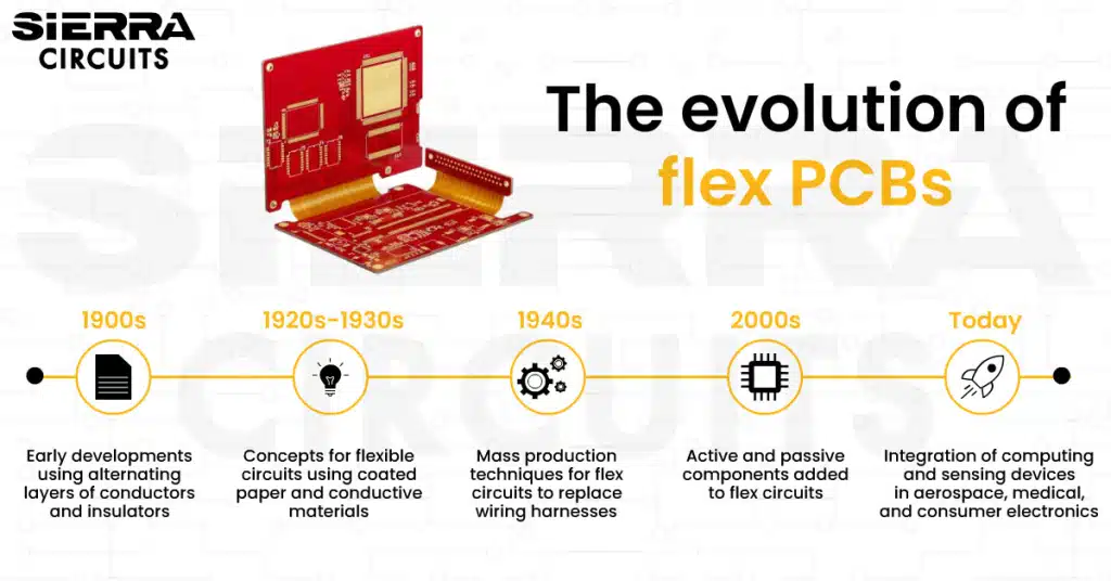
Flex circuit boards date back to the early 20th century, with early developments focused on creating flexible circuits using alternating layers of conductors and insulators.
At the beginning of the 20th century, early researchers in the burgeoning telephone industry saw the need to alternate layers of conductors and insulators to produce standardized, flexible electric circuits. An English patent from 1903 describes coating paper with paraffin and laying flat metal conductors to provide the circuits.
Around the same time, Thomas Edison’s notebooks suggested coating linen paper with cellulose gum, then tracing circuits on the gum with graphite powder. The 1947 publication “Printed Circuit Techniques” included a brief discussion of creating circuits on flexible insulating materials such as paper. In the 1950s, Dahlgren and Sanders made significant strides in developing and patenting processes for printing and etching flat conductors on flexible base materials as a way of replacing wire harnesses.
More recently, the integration of active as well as passive components into flexible circuits has led to the development of “flexible electronics,” which involves integrating both active and passive functions into the device.
The combination of traditional advantages found within flexible circuit construction and onboard computing and sensing capability has led to exciting developments in several areas, most especially in applications in the aerospace, medical, and consumer electronics fields.
What are the applications of flex PCBs?
Flex boards are used in aerospace, medical devices, consumer electronics, and automotive applications to enable lightweight, compact, reliable, and flexible electronic connections.
1. Aerospace
The heads-up display (HUD) as used in aerospace is a familiar technology with a clear purpose: displaying operational data directly in the pilot’s field of vision alleviates the need to look away from a potential target to read critical operational data during flight.
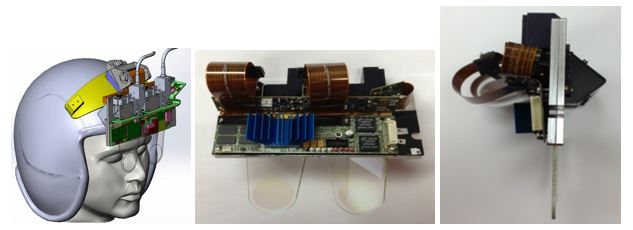
A recent extension of the HUD, applied to wearable technology, provides remote 3D holographic images in a flip-down visor mounted to a helmet. The holographic waveguide helmet-mounted display (HWVD) from HoloEye Systems provides high-resolution true 3D imaging, using flexible PCB cables to drive the waveguide optical system, which uses HoloEye’s liquid crystal on silicon (LCOS) display technology.
The flexibility, reliability, and performance of the flex PCB cables make the HWVD effective in realtime use for avionics, and the light overall weight makes it feasible to mount the display directly on the pilot’s helmet, instead of in the aircraft.
2. Medical
A medical device company utilizes flex PCB designs as important components of a new class of hearing-assist devices, providing a higher range and resolution (125 Hz to 10,000 Hz) than currently available hearing devices.
The underlying premise is revolutionary: a small photoreceptor and micro-actuator are placed inside the ear canal, with the micro-actuator in contact with the eardrum. Outside the ear, as in conventional hearing devices, a microphone captures the sound, and a digital signal processor (DSP) converts it to digital signals to be sent into the ear.
But here’s where things get exciting: the digital signals actuate an infrared laser located inside the ear canal, which in turn excites the photoreceptor, turning the digitized audio into a small current that drives the micro-actuator, causing the eardrum to vibrate.
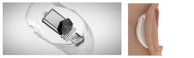
Flex PCB design permitted the engineers to mount the microphone, DSP, and battery in a tiny, compact package that fits behind the ear and allows the laser to provide both power and signal to the passive photoreceptor and micro-actuator. While this is currently still an investigational device, the technology is promising and exciting.
To know the applications of flex PCBs in the medical industry, read why are flex PCBs used in medical devices and wearables?
3. Consumer electronics
The number of applications and uses for flex PCBs within the consumer industry is too exhaustive to list. But simply put: if you wear it, carry it, or drive it, there’s a good chance it has flexible PCBs in it.
The first flex PCB most people think of is typically the connector between the keyboard and screen of a laptop. Similarly, flip phones use flex PCBs to connect the two halves of the phone.
The moving print head of modern printers uses flex PCBs in place of the older-style ribbon connectors; likewise, the read/write head of disk drives, which requires billions of flexing operations during the product’s lifecycle, has benefited from the increased reliability and cost-effectiveness of flex PCBs.
4. Automotive
Automotive applications, in particular, carry a number of advantages, not only in the usual arena of reliability but even more so for the weight savings that a flex board offers compared with a standard PCB and wiring harness.
Weight is the enemy of fuel efficiency (or range, for electric/hybrid vehicles), and flex PCBs greatly reduce the labor involved in manufacturing a traditional automotive wiring harness. And the inherent resistance of flex circuit boards to vibration makes them ideal for the harsh environment inside a motor vehicle.
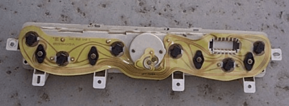
Whether for cost reduction, longevity, improved product quality, or performance, flexible PCBs offer an effective way to connect the various modules of an electronic system.
Read why are flex PCBs used in satellite applications to learn how flexible circuits cut weight and boost durability in satellites.
Flex classification is crucial for identifying the type of flexible printed circuit board you are designing. Make sure you know what the standards and requirements are before beginning your design. This will save you time and effort in the long run. Let’s delve a bit deeper into what the different flex classes and types are, as well as the differentiators for both.
Sierra Circuits fabricates and assembles high-performance flex PCBs engineered to withstand harsh environments and support dynamic applications.
For more details, see flex and rigid-flex PCB capabilities.
How are flex boards classified?
Flex circuit boards fall into three classes based on the level of inspection and testing required and the performance requirements of the finished product.
| Class | Suitable for | Description | Characteristics | Application |
|---|---|---|---|---|
| Class 1 | General electronic products | Used in applications where cosmetic imperfections are not important, and the primary requirement is the function of the completed printed board. |
|
|
| Class 2 | Dedicated service electronic products | High performance and extended service life are required, while uninterrupted operation is desired but not critical.
|
|
|
| Class 3 | High-reliability electronic parts | Includes equipment and products where continued performance on demand is critical. Equipment downtime cannot be tolerated, and it must function reliably when required. |
|
|
To know more about flex board manufacturing class, read our article choosing IPC class for medical flex PCBs.
What are the types of FPCs?
Flex printed boards are available in five IPC types based on their conductive layers, construction, materials, and plated-through holes.
| IPC type | Description |
|---|---|
| IPC type 1 | Single-sided flexible printed circuit board. This is the most common type of flex circuit, ideal for dynamic flex applications. Contains one conductive layer. Can be found with and without stiffeners. SMT lands are accessible only on one side. |
| IPC type 2 | Double-sided flexible printed circuit boards. Contains two conductive layers with plated-through holes. Can be found with or without stiffeners. Copper is bonded on both sides of the base material, then drilled, plated, etched, and insulated on both sides by a top and bottom dielectric cover layer. |
| IPC type 3 | Multilayer flexible printed circuit board. Contains three or more conductive layers with plated-through holes. The plated-through holes are used to create the interconnection of the conductive layers. Can be found with or without stiffeners. |
| IPC type 4 | Multilayer rigid and flexible material combinations containing three or more conductive layers with plated-through holes. |
| IPC type 5 | Flexible or rigid-flex printed circuit boards. Contains two or more conductive layers. No plated through-holes. |
What makes Sierra Circuits’ flex PCBs and processes unique
Sierra Circuits is an experienced, reliable manufacturer of flex boards. What is special about how we approach flex? For starters, we serve as a single point of contact throughout the entire process of quoting, designing, ordering, manufacturing, and delivery. Plus, our flex PCB solutions have several key differentiators that make them suited for several use cases:
- We produce only the highest quality boards, with polyimide film and thin copper foils on trace and space as small as 50 microns. Our process has been honed over nearly 30 years to provide a one-stop shop that meets all your PCB requirements, from in-house fabrication to turnkey services.
- Our top-of-the-line flex PCBs have already proven themselves in applications in a wide range of industries and devices. Our boards have been used in handheld as well as implantable medical equipment. They can also be implemented in aerospace and automotive applications or in consumer electronics such as laptops.
- In addition to flex PCBs, we also make rigid-flex and high-density interconnect (HDI) flex circuit boards. Rigid-flex boards bridge traditional and flex designs and are often used to connect several rigid-flex boards using flexible circuits. HDI for flex printed circuit boards may be needed to free up more space for other features on the board and make the most of the small package size.
Something else that sets Sierra apart is the level of assistance we offer during the design process.
Need assistance with your layout? Check out our PCB design support. Our engineers can help you with material selection, stack-up, component placement, and routing.
When manufacturing flex printed boards, we use only state-of-the-art machinery for the completion of crucial tasks such as laser drilling and direct imaging. All of our design, manufacturing, and assembly are done in a spacious, high-tech facility in Sunnyvale, California. From here, we offer an easy-to-reach point of contact along with quick turnaround times for the leading tech giants in the area. Sierra is also ISO 9001:2008, ISO 13485:2003, MIL-P-55110, and RoHS certified.
Check out flex PCB capabilities to learn more.
Flex printed boards offer a lightweight, reliable solution for connecting complex electronics in compact and demanding applications. With the right class and IPC type, you can select a flex board that meets your design and performance requirements.





Start the discussion at sierraconnect.protoexpress.com