


Contents
PCB designers have to consider various design parameters in order to design a successful board. To ensure their design is accurate, designers can use circuit simulation to understand the dynamic behavior of their circuits leading to efficient circuit board design.
What is circuit simulation?
Circuit simulation is a process used to check and verify the functionality of electrical/electronic circuit designs before manufacturing and product deployment. It is used for a broad range of applications ranging from microelectronics and integrated circuits to power electronics and electrical power distribution networks. Circuit simulation can be run on linear and non-linear circuits according to the requirement.
Circuit simulation includes:
- Mathematical modeling of the circuit elements, or devices.
- Formulation of the circuit/network equations.
- Techniques for the solution of these equations.
Linear and non-linear circuits
A linear circuit is where the current flowing through the circuit is directly proportional to the circuit voltage. The relationship between current and voltage in a linear circuit is as shown in the graph below:

A non-linear circuit is when the current flowing through the circuit is not directly proportional to the voltage in the circuit, leading to a graph of voltage vs. current looking like a curve.

Also read, Network Theory for Better PCB Design and Development.
How does circuit simulation work?
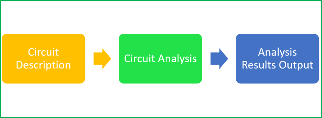
Circuit simulation works by designing a circuit using a schematic editor and subjecting the circuit representation to either constant or varying inputs. The resulting signal outputs are recorded and analyzed.

A circuit simulator is meant to emulate the behavior of circuit components to achieve signal outputs identical to the circuit if it was actually in operation.
Device model
A device model is an analytical expression generated using theoretical and experimental studies. Variables and constants that constitute this analytical expression are known as model parameters. Also, device parameters are those that are used to replicate the actual component characteristics on a simulator.
IBIS model
IBIS (Input/Output buffer information specification) is a behavioral model that details the electrical characteristics of the digital inputs and outputs of a device. This is done using V/I (voltage versus current) and V/T (voltage versus time) data without divulging any proprietary information. The IBIS models are meant to be used for signal integrity analysis on systems boards.
What are different types of simulation?
In this article, we focus on analog circuit simulation. Here are the types of circuit simulation:
Analog simulation
The analog circuit simulation process includes using precise representations of an electronic circuit to get accurate signal outputs corresponding to the inputs. The models used for circuit simulation can either be linear or non-linear as explained previously. Analog circuit simulations can be executed in various modes such as:
- AC (frequency domain)
- DC (non-linear quiescent)
- Transient (time-domain)
Analog simulators use algorithms to analyze the circuit behavior in different modes. Such algorithms employ the process of solving matrices to predict circuit performance. In analog simulations, signals are propagated as continuously varying values.
Digital simulation
Digital circuit simulation includes the use of circuit behavior models that are generated using hardware description language (HDL). In this method, unlike analog simulation, discrete voltage values, mainly logic 0 and logic 1 are propagated. The techniques for such signal propagation come with varying accuracy for different values of the propagation delay of the logic levels in the circuit. This technique allows for the simulation of much larger circuits in lesser time and with the use of fewer computational resources when compared to analog simulation.

High-Speed PCB Design Guide
8 Chapters - 115 Pages - 150 Minute ReadWhat's Inside:
- Explanations of signal integrity issues
- Understanding transmission lines and controlled impedance
- Selection process of high-speed PCB materials
- High-speed layout guidelines
Download Now
Mixed-signal simulation
The mixed-signal simulation approach integrates both analog and digital simulation techniques. The circuit, in this case, is divided into two distinct systems (analog and digital) for appropriate analysis in each circuit segment. The digital simulation is kept event-driven whereas the analog signals are retained as they are.
To enhance your understanding of PCB simulation and design challenges, watch our interview, PCB layout, model extractions, and simulations by Matthew Harms.
You can book a meeting with our experts or call us at +1 (800) 763-7503.

Circuit analysis types
A circuit simulator runs various types of analysis, giving different information about the circuit. Here are a few types of circuit analysis:
Transient analysis
Transient analysis refers to the circuit analysis during the period that it changes from one steady-state condition to another. Electrical circuits are subjected to rapid changes when switches are opened or closed, or when there is a sudden change in source, etc. When such a change happens, the circuit which was in a distinct steady-state condition will move to another steady-state condition. This time between two steady-state conditions is called a transient period. Transient analysis is used to learn how parameters such as current and voltage will change during a transient period.
Transfer function analysis
A transfer function of an electronic circuit is a mathematical function that is used to theoretically model the device output for every possible input. The transfer function can be represented in the form of a graph by plotting the input vs. output, to get what is known as a transfer curve. This is referred to as transfer function analysis.
Noise analysis
Signal noise refers to unwanted variations in current or voltage that are usually random and of small amplitude. Every electronic component generates signal noise, and such noise can be from an internal or external source. The noise in a circuit can be measured using the parameter called signal-to-noise ratio (SNR) . The signal-to-noise ratio can be defined as the ratio of the required signal to the undesired signal or noise. SNR is measured in decibels (db).
Operating point analysis
The operating point is a particular point within the operation characteristic of an electronic component. Analysis using operating point is carried out for circuits with constant sources, where the voltage and current are constant. The operating point can be physically measured using a digital multimeter, or in a simulation, it is measured by selecting the component of interest in the software.
Which software is used for circuit simulation?
SPICE (Simulation Program with Integrated Circuit Emphasis) is a popular open-source circuit simulation engine. It accepts a netlist that describes the circuit to perform various simulations. A netlist is text that describes every component used in the circuit and to where they connect. LT spice is another open-source circuit simulation software similar to SPICE.

Circuit simulation using Analog Devices Inc. LTspice®
Here are some basic circuits and their analysis:
DC analysis
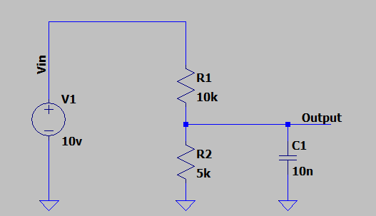
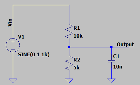
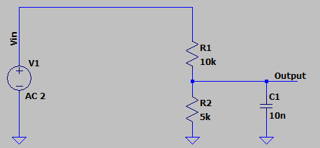
First, we will look at a simple voltage divider circuit. It has a 10V DC input across 10k and 5k ohms resistors. There is also a capacitor at the output.
If we look at the input and output DC levels, we will get a plot like this
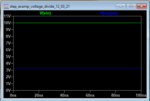
Here the output voltage V(output) is 3.333V.
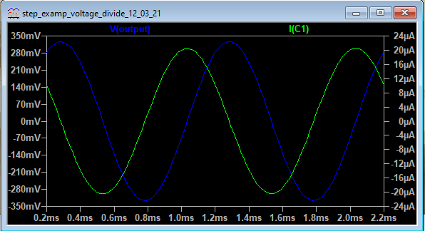
Now let’s change the input from a DC to a sine wave of amplitude 1V and 1kHz frequency and analyze the voltage and current across the capacitor.
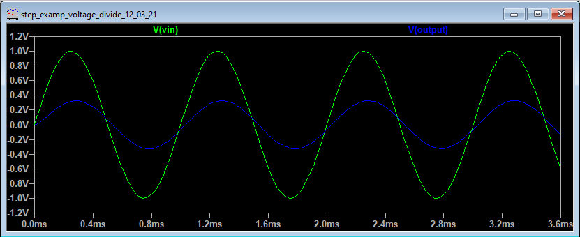
These are the input and output voltages. We can also plot the current and power drawn through any component.

The current through the capacitor C1 is lagging behind the voltage.
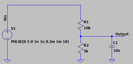
Now, let us give a pulse input. We will select a pulse of time period 1ms with a rise time and fall time of 10ns, amplitude 5V, and on time of 0.2ms.
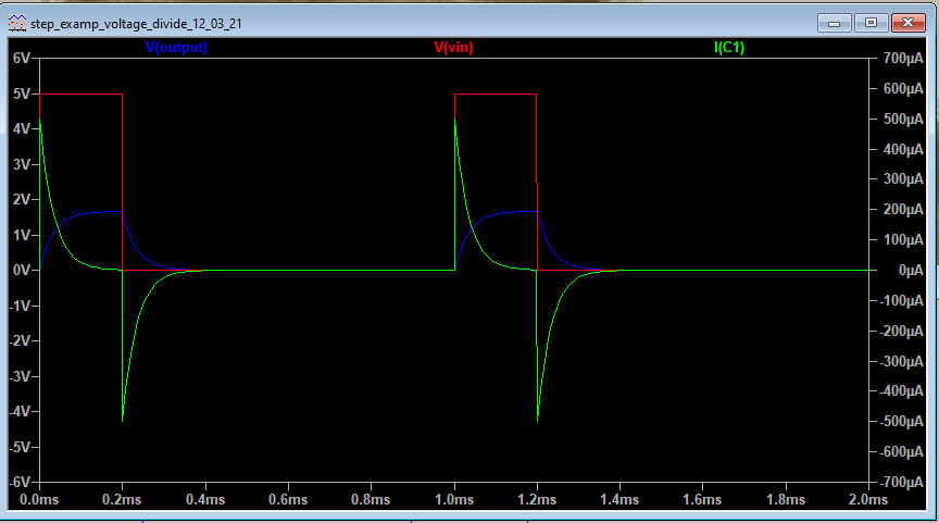
In the output, we can observe the voltage rising across the capacitor (blue curve) when the input is on and the input voltage is 5V ( red curve). The current in the capacitor (green curve) rises sharply with a positive current and slowly becomes zero as the capacitor charges. When the voltage becomes zero the capacitor discharges and the current is negative which slowly drops to zero.
AC analysis
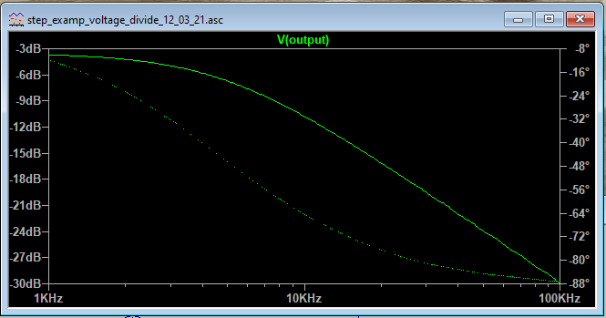
Now let’s run an AC analysis
Here we need to specify the sweep type, the number of readings, the start, and end frequency to run the AC analysis of the circuit.
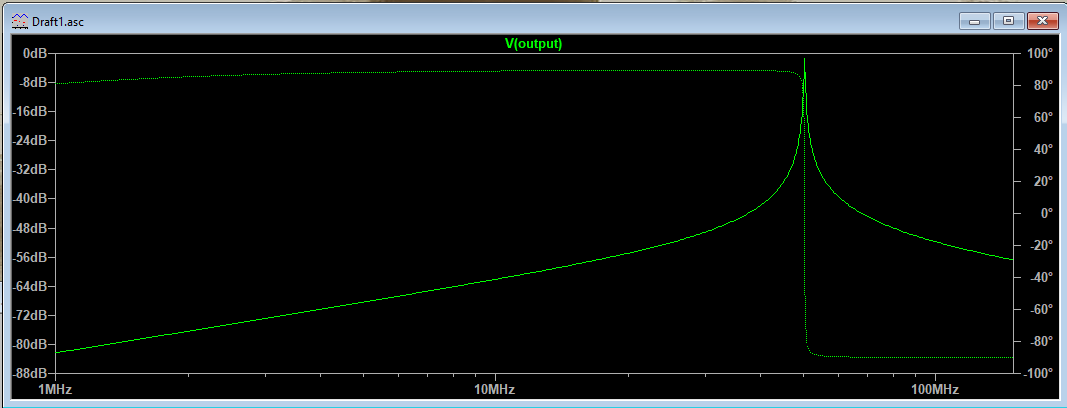
Let us look at a circuit that is a bit more complex like an LC bandpass filter with a center frequency of 50MHz.
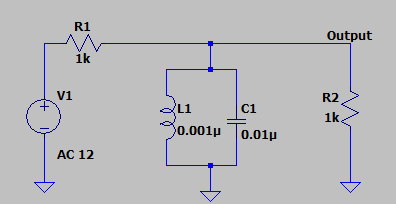
Now we will set up an AC sweep. Once we plot the output we can see the attenuation at different frequencies and center frequency at around 50MHz.
Also read, how to reduce signal attenuation in high-speed PCBs.
Circuit simulation is an invaluable tool for PCB designers to understand circuit behavior before board fabrication. The use of circuit simulation can help prevent expensive PCB rework and design inefficiencies.
Want to know more about circuit simulation? Let us know in the comment section below.

Design for Manufacturing Handbook
11 Chapters - 96 Pages - 90 Minute ReadWhat's Inside:
- Annular rings: avoid drill breakouts
- Vias: optimize your design
- Trace width and space: follow the best practices
- Solder mask and silkscreen: get the must-knows
Download Now


