


Contents

On-demand webinar
How Good is My Shield? An Introduction to Transfer Impedance and Shielding Effectiveness
by Karen Burnham
The study of resolving issues with electrical circuits and networks is called network theory. Network theory concepts are essential for network analysis which is critical for the design of PCB transmission lines and power distribution networks. You need to grasp the fundamentals of electrical circuits and network components to master network analysis.
Knowledge of network concepts is also critical to ensure streamlined PCB manufacturing processes. Here are a few concepts central to network theory that we will discuss through the course of this article:
What is the difference between electrical networks and circuits?
The major difference between a network and a circuit is that a network does not require a closed path for current and a circuit does.
Electric network
An electrical network includes interconnected electric circuit elements including capacitors, resistors, inductors, and switches.
Electric circuit
An electric circuit includes a closed path to facilitate a flow of electrons from a power source supplying current or voltage. Also, circuit elements can either be connected in series or in parallel or as a combination of series or parallel. Electrical circuits are a subset of electrical networks.
Types of network elements
You can group network elements into different types depending on various parameters:
- Active and passive elements
- Linear and non-linear elements
- Bilateral and unilateral elements
Active and passive elements
When network elements need power to function it is known as an active element. Examples include microprocessors, opamps, etc. Passive components are those which cannot be controlled by other signals and can absorb or store energy. Examples include resistors, inductors, and capacitors.
Linear and non-linear elements
When network elements display a linear relationship between voltage and current they are known as linear elements. These include capacitors, inductors, and resistors. When elements of a network do not show a linear relationship between voltage and current they are called non-linear elements. These include diodes, transistors, etc.
Bilateral and unilateral elements
Here network elements are classified according to the direction of current flow through the elements.
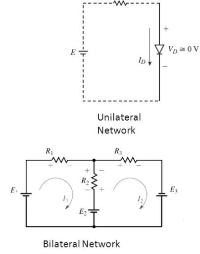
Unilateral elements allow the unidirectional flow of current. They provide different impedance in both directions. Bilateral elements allow current flow in both directions and provide the same impedance in both directions of current flow. These include components such as capacitors, resistors, and inductors.
Also, read S-parameters Measurement Using a Vector Network Analyzer
Network theory terminology
Here is a list of terminologies central to Network Theory:
Current – The time rate of charge flow is called current and is denoted by “I” measured in Amperes (Coulombs/second).
Electron current flows from the negative to the positive terminal of the power source. This is obtained from the movement of free electrons.
Conventional current flows from the positive to the negative terminal of the power source and is generated from the movement of free positive charges.
Voltage – The electromotive force that results in charge flow is called voltage. It is denoted by “V” and measured in Volts

Reactance is a combination of capacitance and inductance in an AC circuit. This is denoted by X, with the inverse (1/X) being the susceptance (b).
Impedance is the combined result of inductance and capacitance in an AC, denoted by Z. This inverse (1/Z) is called the admittance Y.
Resistance in a circuit denoted by R. The reciprocal of resistance (1/R) is conductance denoted by G.
Capacitance of an electrical network is denoted by C.
Inductance within an electrical network is represented by L.
Ohm’s Law
Ohm’s Law states that the current through a conductor between two points is proportional to the voltage across the two points.
R = V/I where R is the proportionality constant called resistance. V denotes the voltage and I is the current.

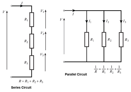
Series and parallel circuits
The most fundamental type of network is either in series or parallel. When it comes to a series circuit, the aggregate resistance/impedance is the sum of resistances or impedances. Also, in parallel circuits, the reciprocal of the resultant equivalent resistor (1/R) is equal to the sum of the reciprocals of resistances connected in parallel (1/R = 1/R1+1/R2+1/R3…).
In a series circuit, the voltage is the sum of voltages across each network element whereas the current across each element is the same. When you consider a parallel circuit, the voltage remains the same across each network element whereas the current is in inverse proportion to the resistance/impedance of every circuit.
Inductors follow the same principle as resistors with regard to impedance and voltage that is (L = L1+L2+L3…) for series inductors. For capacitors in parallel, (C= C1+C2+C3).
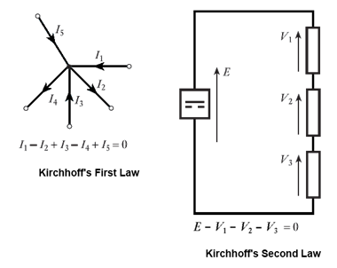
What are Kirchhoff’s laws?
Kirchhoff’s circuit laws deal with the relation between current and voltage in electrical circuits.
Kirchhoff’s first law also known as Kirchhoff’s current law states that the sum total of currents at a circuit node is equal to zero.
The second law of Kirchhoff states that the sum total of voltages around a loop equals zero.
What is a network theorem?
A network theorem is a provable statement that can be applied to solve circuits for voltages and currents. Here are some frequently used network theorems:
Tellegen’s theorem
Tellegen’s theorem states that the sum total of power in all branches of a network equals zero, provided the network also conforms to Kirchoff’s Laws. For a network with b number of branches:
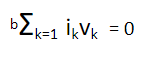
This is widely applicable to a broad range of problems and it holds good for every type of network element – passive, active, linear, and non-linear.
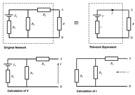
Thévenin’s theorem
Thévenin’s theorem states that any set of network elements in a circuit can be replaced by a single voltage source and series resistor connected to a load. The corresponding voltage is determined by having the branch open circuit, and in case of resistance is computed by short-circuiting all voltage sources.
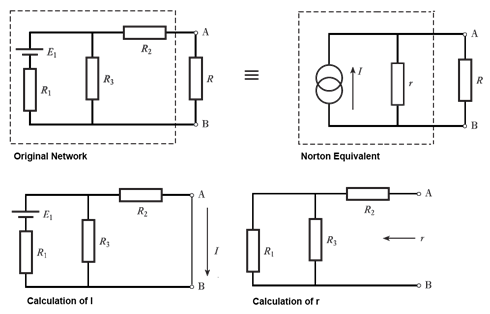
Norton’s theorem
Norton’s theorem states that any set of network elements can be represented by an individual current source and parallel resistor. You can calculate the corresponding current by short-circuiting the branch. Also, you can determine the resistor value by shorting out any voltage sources.

Superposition theorem
Superposition lets you find a solution by considering each current or voltage source individually and summing up the results. This is useful when a network contains more than a single current or voltage source. In order to consider every source individually, other existing voltage sources are shorted out and current sources are set to an open circuit.
Need help in designing reliable PCBs? Our engineering team can help you with thermal management, stack-up design, and DFM analysis.
You can book a meeting with our experts or call us at +1 (800) 763-7503.

What are the different types of network analysis?
Network Analysis is a structured method to mathematically analyze a network. This is useful to engineers in solving circuits with multiple component configurations and sources of power and voltage. Also, performing network analysis enables designers to weed out inefficiencies in circuits and streamline the network design. This requires a strong command over network theory concepts. You can also implement network analysis to facilitate network reduction techniques in electrical circuits which are needed to minimize the size and complexity of circuits.
Here are a few methods for network analysis:
Nodal analysis
Nodal analysis is a method to analyze circuits using Kirchoff’s first law. You define node voltages as the variables in nodal analysis to find solutions. These are the steps to carry out nodal analysis:
- Assign voltage to every node as V1, V2, etc.
- Calculate the current in every branch such as node1 to node2, Resistance denoted as R12, Current in the branch is calculated as I12 = (V1-V2)/ R12
- Apply Kirchhoff’s first law at every node
- Solve the resultant equations to get the voltages at every node
Mesh analysis
Mesh analysis is a method that is used in network analysis to calculate currents in planar circuits. You can depict planar circuits on a plane surface without criss-cross connections. The steps to conduct mesh analysis are as follows:
- Assign a mesh or loop current to every closed loop in the network
- Apply Kirchhoff’s second law to every loop
- Solve the resultant equations to determine the loop currents and in turn the network voltages
Network topology in electrical circuits
Network topology is the graphical representation of electric circuits and is useful in analyzing complex electrical circuits. It is also known as graph theory and is an integral part of network theory.
Also read, an article on the Role of PCB Trace Current Capacity in Design
What is a network graph in network analysis?
A Network graph includes a group of nodes connected through branches and a node is an intersection point for two or more branches. Also, you can define a branch as a line segment that connects two separate nodes.
You can transform all electrical circuits or networks into equivalent graphs by interchanging passive elements and voltage sources with short circuits. You will also need to interchange current sources with open circuits. Hence line segments in the network graph either represent voltage sources of the electric circuit or passive elements.
Network Theory concepts are vital when it comes to PCB design. Aspiring PCB designers and even established professionals need a good understanding of network theory to design efficient networks and PCBs.

High-Speed PCB Design Guide
8 Chapters - 115 Pages - 150 Minute ReadWhat's Inside:
- Explanations of signal integrity issues
- Understanding transmission lines and controlled impedance
- Selection process of high-speed PCB materials
- High-speed layout guidelines
Download Now


