Contents

On-demand webinar
How Good is My Shield? An Introduction to Transfer Impedance and Shielding Effectiveness
by Karen Burnham
Rigid-flex PCB designs may be expensive to fabricate, but they can essentially save costs during electronic system assembly.
A straight line is not always the shortest route between two points in electronic products: Thanks to rigid-flex PCB architecture, circuits can be folded onto themselves with 180º bends—superimposed at minimum height—thereby shrinking product dimensions.
What is a rigid-flex PCB?
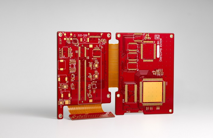
A rigid-flex PCB is a combination of rigid and flexible technologies. In this type of PCB, one or more flex circuits are used to connect sub-circuits in rigid PCBs. The flexible section of the rigid-flex PCBs is generally multi-layer circuits. Padded through-holes are used to secure the interconnectivity among these layers.
How do rigid-flex PCB cuts assembly costs?
Using rigid-flex PCBs in your projects can make way for both direct and indirect cost savings. Direct cost savings mainly comes from reduced Bill of Materials and inventory. Indirect cost savings are from reduced assembly costs and improved reliability.

Let us assume that a product has 6 interconnected rigid PCBs (Power board, two control boards, and three display boards). Interconnections among these boards would require wire harnesses and connector pairs. Now, let us have a look at how using rigid-flex PCB could reduce direct and indirect costs.
Direct cost savings
A single rigid-flex PCB with 6 rigid sections could be used to replace the entire assembly of 6 rigid PCBs within the product. It also replaces the wire harnesses and eliminates the requirement of connector pairs. This inventory reduction leads to direct cost savings.
Indirect cost savings
Since there are no wiring harnesses involved in rigid-flex PCBs the cost incurred in assembling them is saved. Also, no wiring harnesses mean there are no wiring errors which increases the reliability of the product. This eases out the testing procedure which also reduces the assembly costs.
In order to prevent unnecessary expenditure and create a highly cost-effective rigid-flex board, it is imperative to consider the common DFM mistakes in rigid-flex PCBs and employ strategies to mitigate these issues right from the design phase.
Materials used in rigid-flex PCBs
Rigid-flex PCBs use a combination of rigid and flex materials. The materials include core, prepreg, copper foil, flexible laminates, cover layers, and bond plies.
The PCB material used in flex sections can be just a few microns thick but can be reliably etched. This often makes them preferable over rigid PCBs in satellite and aerospace applications.
To know more about flex PCBs used in satellite applications read our article Flex PCBs in Satellite Applications: Lighter Than the Clouds.
No flow prepregs are one of the most critical components in rigid-flex manufacturing. This type of prepregs prevents the flow of epoxy resin onto the flexible sections of your PCB.
Flex sections in a rigid-flex PCB are built using unreinforced substrates made up of polyimide dielectric film cladded with rolled copper. The rolled copper is more flexible than the copper foil used in the rigid PCBs. For this reason, the cladded base material is first drilled and the holes are selectively plated. Once the holes are plated, the traces and pads are etched. Bondply is used to isolate the conducting layers. Bondply is a layer of polyimide film with adhesive coated on either side. This layer also insulates the outer surfaces of the flex stackup along with ribbon extending to the rigid PCB section.
Flex materials are less dimensionally stable than the rigid materials that are stacked with. Hole to copper clearance must be at least 10 mils. Vias must be placed at least 50 mils away from the edge of the rigid area.
Seek guidance from your manufacturer to develop your PCB stackup and PCB design rules. Variations in the CTE (Coefficient of thermal expansion) among the flex/rigid prepregs would require a careful balance of thicknesses, especially for impedance control in flex designs.

Controlled Impedance Design Guide
6 Chapters - 56 Pages - 60 Minute ReadWhat's Inside:
- Understanding why controlled impedance is necessary
- Stack-up design guidelines
- How to design for impedance
- Common mistakes to avoid
Download Now
How to minimize rigid-flex PCB design costs?
Keep the number of layers as low as possible
Minimizing the number of layers reduces the number of prepregs required to fabricate your PCB. At the same time, a lesser number of layers eases out the PCB fabrication process and hence reduces the overall manufacturing cost.
Use rigid board laminates to achieve the overall thickness
To achieve a specific overall thickness, it is always advised to use rigid laminates, rather than using additional no-flow prepregs. The rigid laminates are of a lower cost when compared to no flow prepregs.
Ensure that flexible arms in your rigid-flex PCB end in a rigid section
If the flex PCB designer wants one or more flex arms of the flex PCB to end in a flex cable, they require additional mechanical support. This is because these flex connections do not possess the desired thickness or rigidity. This incurs the cost of protecting these flex layers during the fabrication process. Hence having all the flexible arms ending in a rigid section will reduce the overall cost of your rigid-flex PCB design.
For more tips on rigid-flex design, see IPC-2223 standards and design violations for rigid-flex boards
Design advantages of flex section in rigid-flex PCBs
Flex section of your rigid-flex PCBs unlock many physical design advantages, they include:
- 360-degree bendability. This is one of the prime reasons for the flex circuits to be used in medical devices and wearables.
- Superior resistance to vibrations and other disruptions within harsh environments.
- Support for compact, lightweight design; product weight can be greatly reduced.
- Small, flexible cables that take up less space than typical wires.
- The ability to be warped or contorted without any associated breakage.
To know more about flex PCB applications read our article Why Are Flex PCBs Used in Medical Devices and Wearables?
On the electronic product manufacturing side, rigid-flex PCBs are similarly advantageous.
- They permit better airflow and heat dissipation than many other PCBs.
- Assembly costs are much lower than those for traditional wiring harnesses.
- Less overall susceptibility to assembly errors, since the manufacturing process is streamlined and standardized, without the problematic manual input required for building many of these harnesses.
- Eases out the testing procedure. The ability of the rigid-flex PCBs to eliminate connectivity issues before the components are assembled, prevent unnecessary wastage and expenses.
Flex trace routing in your rigid-flex PCB
Trace routing in the flex area should be curved, not angled, to increase peel strength. This recommendation is opposite the routing practice for rigid boards. To increase ribbon flexibility, planes should be cross-hatched; however, the cross-hatch complicates impedance control. Again, a careful balance is required. Traces on different layers should be staggered vertically, not placed atop each other, to increase ribbon flexibility.

To know more about flex design considerations read our article Avoiding Common Flexible PCB Errors and Designing for Success.
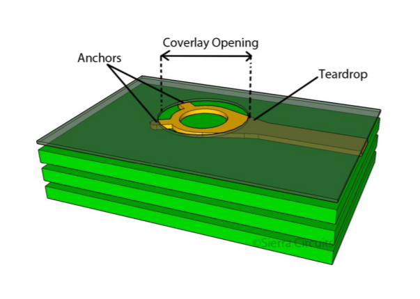
Annular rings should be as large as possible in flex-only regions to reduce the risk of peeling, and the transition from the annular ring to the trace should be teardrop-shaped for the same reason. Adding tabs or anchors also helps to prevent peeling.
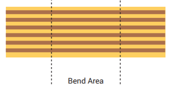
Traces should always be perpendicular to the fold in the flex areas that will be bending. Where flex ribbons have sharp interior corners, tear stops should be added. Copper can be incorporated during layout at the elbow of those corners for reinforcement or polyimide stiffeners can be specified for the inside corner radii. The stiffeners can be laminated when the cover-coat is bonded and are the preferred method to prevent tears. The best strategy is to avoid using sharp corners in a flex design.
A very basic checklist for rigid-flex designs includes these routing considerations:
- The flex traces should be staggered vertically as shown below.
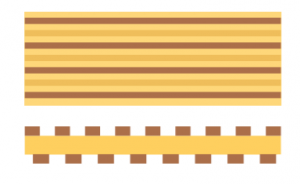
- The traces should be curved. Sharp edges along the traces should be avoided.

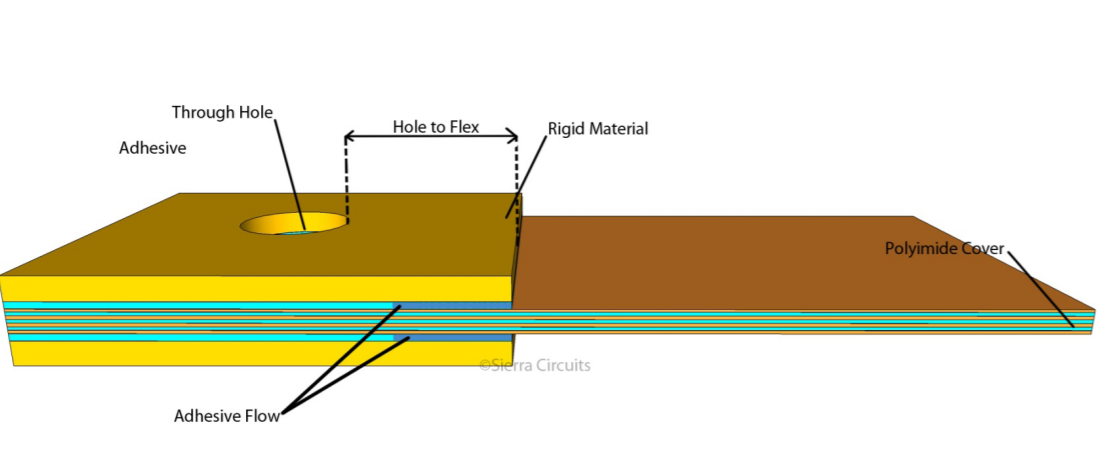
For rigid-flex designs, hole to flex distance is important. That is the distance between vias and the rigid-flex transition area. Avoid going below 50 mils for high-reliability applications. Keep in mind the rule most broken in rigid-flex designs: most manufacturers will not allow less than 30 mils for commercial applications.
- Keep the number of flex layers as low as possible.
- Sierra recommends placing flexible layers within rigid layers when designing rigid-flex boards. The layer number should always be even.
- Drill to copper should be 10 mils. Drill to copper is very important on rigid-flex.
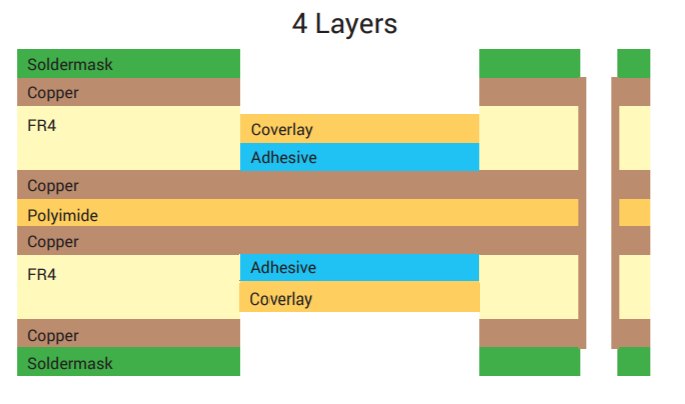
A sample 4 layer rigid-flex stackup is shown below.
Remember, rigid-flex PCB designs may be expensive to fabricate, but they can save costs during system assembly. The earlier you consult a PCB manufacturer during the planning stages, the better your PCB. The timely involvement of the PCB manufacturer in the design process enables the manufacturer to produce PCBs optimized for your end product. Using rigid-flex PCBs in your design would significantly bring down the assembly costs. Sierra Circuits’ flexible printed circuit board services include flexible prototypes, high-tech quick turn rigid-flex PCBs, and HDI for flex. We offer single-layer, double-layer, rigid-flex, multilayer, and HDI flex PCBs.
To learn more about flex design guidelines, watch our webinar Flex PCB Design Guidelines for Manufacturing.

Flex PCB Design Guide
10 Chapters - 39 Pages - 45 Minute ReadWhat's Inside:
- Calculating the bend radius
- Annular ring and via specifications
- Build your flex stack-up
- Controlled impedance for flex
- The fab and drawing requirements
Download Now
Quote and order your circuit boards online with our Turnkey PRO tools in just a few minutes.
About Amit Bahl : Amit Bahl, widely recognized as the PCB Guy, earned his Bachelor of Science in Engineering from UCLA. He is currently the Chief Revenue Officer at Sierra Circuits, where he continues to lead efforts to simplify the PCB design journey and support designers and engineers in creating high-quality boards.