Contents

On-demand webinar
How Good is My Shield? An Introduction to Transfer Impedance and Shielding Effectiveness
by Karen Burnham
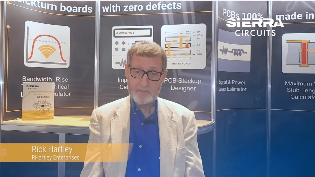
At PCB West 2022, we interviewed Rick Hartley to find out how circuit grounding controls noise and EMI. Watch the whole video to learn about his insights.
What is the purpose of grounding a circuit?
Rick Hartley: There are actually three things that are considered as ground. To begin with, Earth is the real ground. We attach electrical systems to it to divert lightning and other high-energy fields for safety concerns.
Second, the chassis that surrounds our electronics is connected to the ground. But it is not actually ground. It is a Faraday cage that contains the fields of the circuit to prevent EMI problems.
Finally, the reference planes in our board. These are also not ground even when you attach them to the chassis and then to the Earth. Therefore, it’s important to understand what ground actually means.
How does grounding affect the circuit current?
Rick Hartley: Circuit current is developed by the electric and magnetic fields in a transmission line. When a line is situated between a trace and a ground plane, it provides good field containment and control over the current.

PCB Transmission Line eBook
5 Chapters - 20 Pages - 25 Minute ReadWhat's Inside:
- What is a PCB transmission line
- Signal speed and propagation delay
- Critical length, controlled impedance and rise/fall time
- Analyzing a PCB transmission line
Download Now
Problems arise due to improper stack-up. For instance, if the reference plane is two or three dielectric layers away from traces or power, the field spreads and noise gets coupled into the current. To control noise and EMI, have the ground planes one dielectric space away from signal and power planes.
What is the difference between EMI and noise?
Rick Hartley: Whenever one circuit interferes with another, it is called noise. EMI is just a specific source of the noise. For instance, the strong field of the digital circuit can interfere with the analog network when they are on the same board. Similarly, electromagnetic interference is when the circuit energy from a system corrupts the nearby devices. If it is local interference, we call it noise. If it affects other systems, it’s EMI.
How grounding can control EMI and noise in circuit boards?
Rick Hartley: If you have interference in a circuit, it is possible that you have a poor board stack-up where the signal/power is more than one dielectric layer away from a ground plane. This causes grounding issues. In the end, it depends on how well you build the layer stack with the reference planes placed relative to signal and power.
Do you generally ground the positive or negative circuits?
Rick Hartley: Usually, ICs are assembled as per the manufacturer’s guidelines. They have ground pins that are generally connected to the negative side of signals. Most of the signals from integrated circuits are positive, which means they go from zero volts to some higher positive voltage relative to the ground.
In echo and other old emitter-coupled logic circuits, they would ground the positive side to have a negative signal. However, most prefer to ground the negative side.
How do you draw a ground wire in a circuit diagram?
Rick Hartley: The ground is generally shown not as a wire, but as a symbol. You connect all of the points on a circuit board such as capacitors and IC ground pins to the reference plane.
The industry has established specific standards to represent ground in a schematic. But the problem is 99% of the companies that I’ve personally dealt with don’t follow the standards. Most of them will use three lines above one another or a triangle attached to the ground pins.
ANSI defines standards for representing ground points. When you’re not sure how to handle then you should refer to the standards.
Rick Hartley is the principal engineer at RHartley Enterprises and has been in the industry for over 50 years. He is one of the primary consultants for PCB manufacturing and design companies. Rick has also conducted classes on EMI, signal integrity, and various other electrical topics for the last 30 years.
Please comment below if you have any queries on how to reduce the adverse effects of EMI and noise on your board. Our design experts will be happy to help you. Also, visit our design services page to learn more about our capabilities.

Signal Integrity eBook
6 Chapters - 53 Pages - 60 Minute ReadWhat's Inside:
- Impedance discontinuities
- Crosstalk
- Reflections, ringing, overshoot and undershoot
- Via stubs
Download Now


