Contents
Sticking to DFA benchmarks ensures components are correctly assembled on a PCB without any discrepancies. DFA brings down unnecessary production costs by optimizing component selection and identifying potential footprint and BOM errors.
In this case study, you will learn how to overcome the following errors to build a successful board assembly:
- Mismatch between the components’ physical dimensions and footprint
- Inclusion of obsolete or out-of-stock components in the BOM
- Missing component orientation in the PCB design
- Missing datasheet and MPN
- Missing pin markings
Mismatch between the footprint and the component dimensions
A PCB footprint is an arrangement of pads where the component is soldered on a board. It defines the part clearance from the drilled holes, board edges, and other components. An inaccurate land pattern is responsible for faulty component placement.
During the inspection, we discovered the footprints for the components listed below did not correspond to their datasheets.
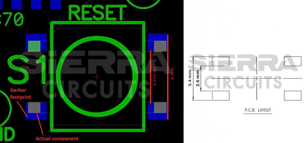
- DTSMW-69N-V-T/R: This is an SMD tactile switch with a 3.5 mm stem height and a rectangular actuator. As shown in the image, the actual component has pad-to-pad dimensions of 2.6 mm and 5.4 mm, whereas the footprint mentioned in the PCB design projects them as 3.395 mm and 6 mm, respectively.
To provide sufficient component spacing, our engineers made changes to the footprint as per the datasheet.
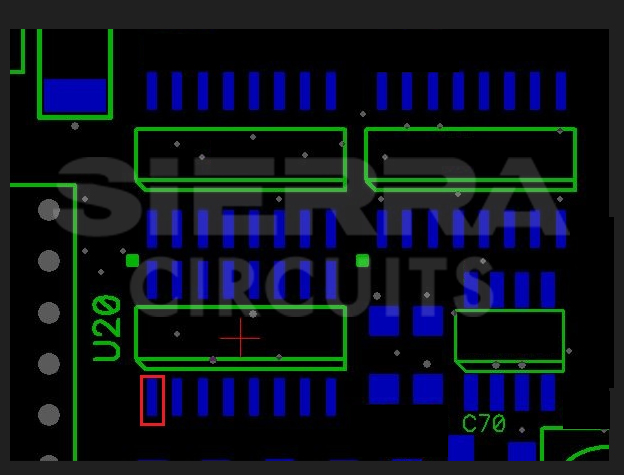
- EPM7128ATC100-12: This programmable logic device (PLD) is based on 3.3-V EEPROM and second-generation multiple array matrix architecture. Here, the footprint provided by the designer does not specify pin-to-pin pitch, pin width, and component dimensions.
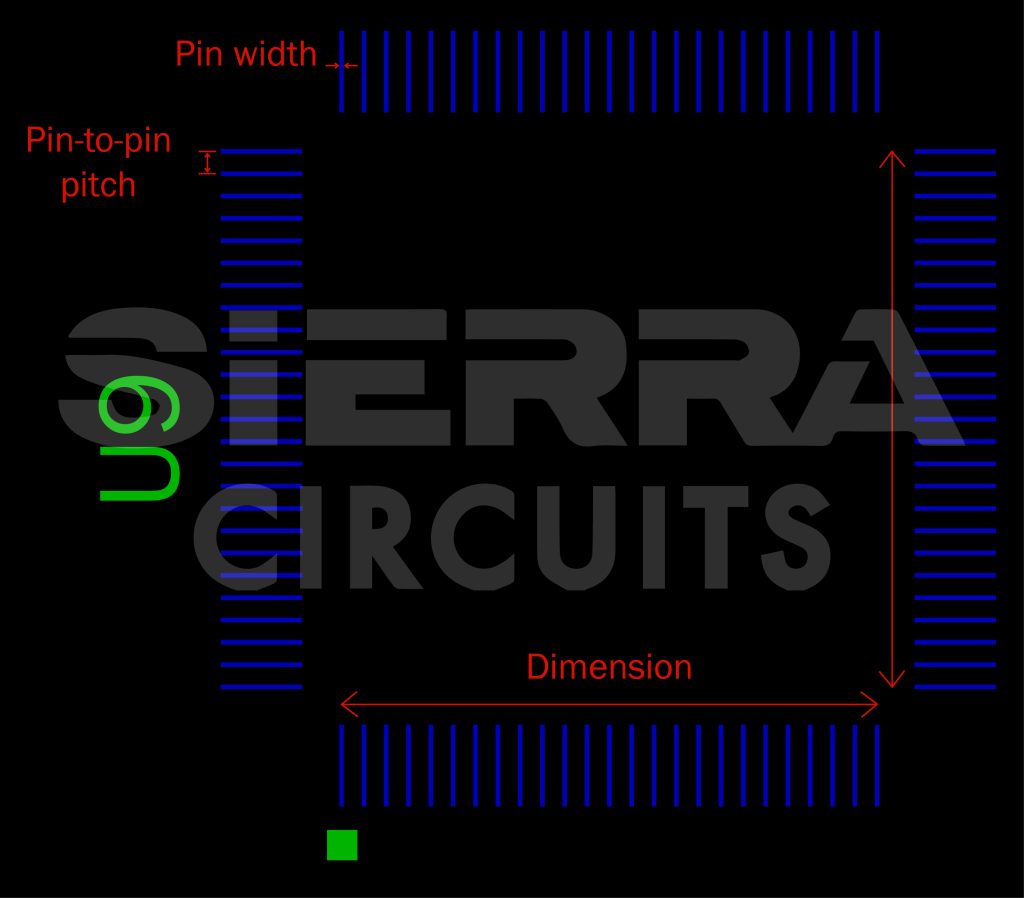
We included the dimensions and pin specifications by referring to the part vendor’s datasheet.
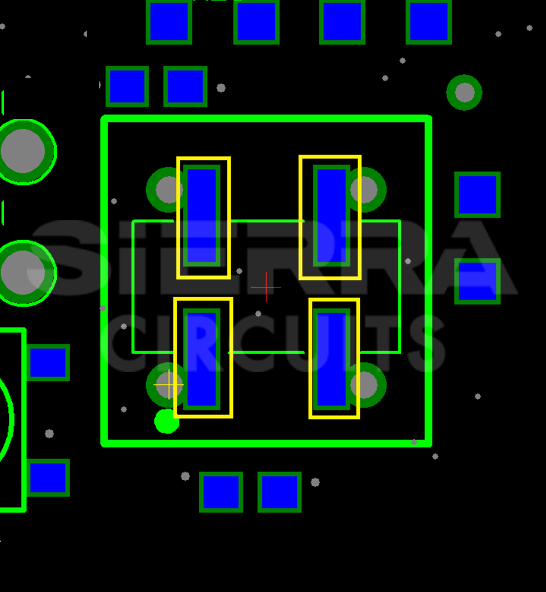
- CPPC4LTBP: This is a 14-pin, programmable oscillator. As per the datasheet, this is a through-hole component with a 30 MHz operating frequency. We identified that the footprint includes SMD pads for this oscillator.
Since this is a through-hole component, we closed the marked pads with solder paste.

PCB Design for Assembly Handbook
6 Chapters - 50 Pages - 70 Minute ReadWhat's Inside:
- Recommended layout for components
- Common PCB assembly defects
- Factors that impact the cost of the PCB assembly, including:
- Component packages
- Board assembly volumes
Download Now
Missing component orientation data
Part orientation and polarity are necessary when assembling components on a PCB. If the components are wrongly placed, it can hamper the functionality of your board. Sometimes, datasheets will not have mounting information. You need to ensure that your datasheet provides part mounting details. For polarized components such as diodes and capacitors, the positive and negative pins should be marked.
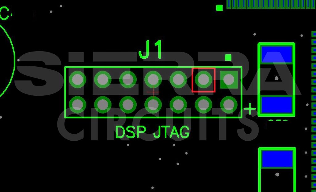
The components mentioned below did not have any direction designated in their datasheets. On inquiry, the customer confirmed the pin 1 and cathode marking as shown in the below images.
- MAX-792TESE: It is a microprocessor supervisory circuit used to control power supply functions. In the footprint, pin 1 was not designated (highlighted in red).
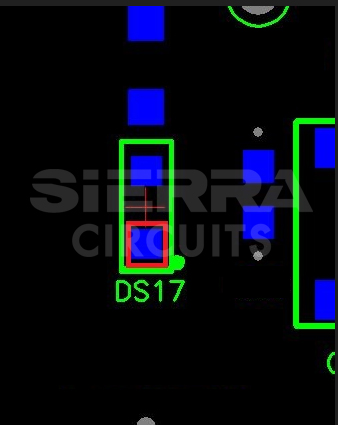
- HDSP-H211: It is an LED display, available as either a common cathode or common anode component.
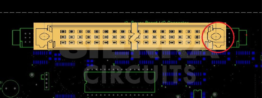
- 650922-5: This component is a board-to-board connector. Pin 1 marking was absent in this case.
- BR1101W: This is an SMT LED. The footprint did not have a cathode marking.
- 87215-4: It is a vertical through-hole connector. Here, the pin 1 marking is present. However, we require the pin 3 marking to ensure the right connectivity with other components.
See 6 design mistakes that lead to PCB assembly errors to learn some of the common design fallacies that lead to PCBA errors.
Missing MPNs in BOM
A BOM lists all the components to be used in a circuit. To build a product, manufacturers rely on a bill of materials to obtain specifications and details for each part. You need to share this list to help the fabricator detect any footprint and BOM errors.
In this design, MPNs for the following parts were not specified in the BOM. We incorporated these components as they were mentioned in the footprint.
- SAFLCS-632-OT: Through-hole DIP socket
- CL21B105KAFNNNE: Ceramic 1µF SMT capacitor

Tool features:
- Provides a preferred BOM format
- Identifies invalid MPNs and obsolete components
- Compares reference designators with their quantity mentioned
Missing datasheets
The primary objective of a datasheet is to verify the components’ specifications. It provides information related to footprints, dimensions, spacing requirements, and tolerances.
For the following components, the datasheet was not provided. Therefore, we followed the datasheets provided by the vendors for these parts.
| Components' MPN | Part details |
|---|---|
| RC1206FR-07422RL | SMT resistor of 422 Ω |
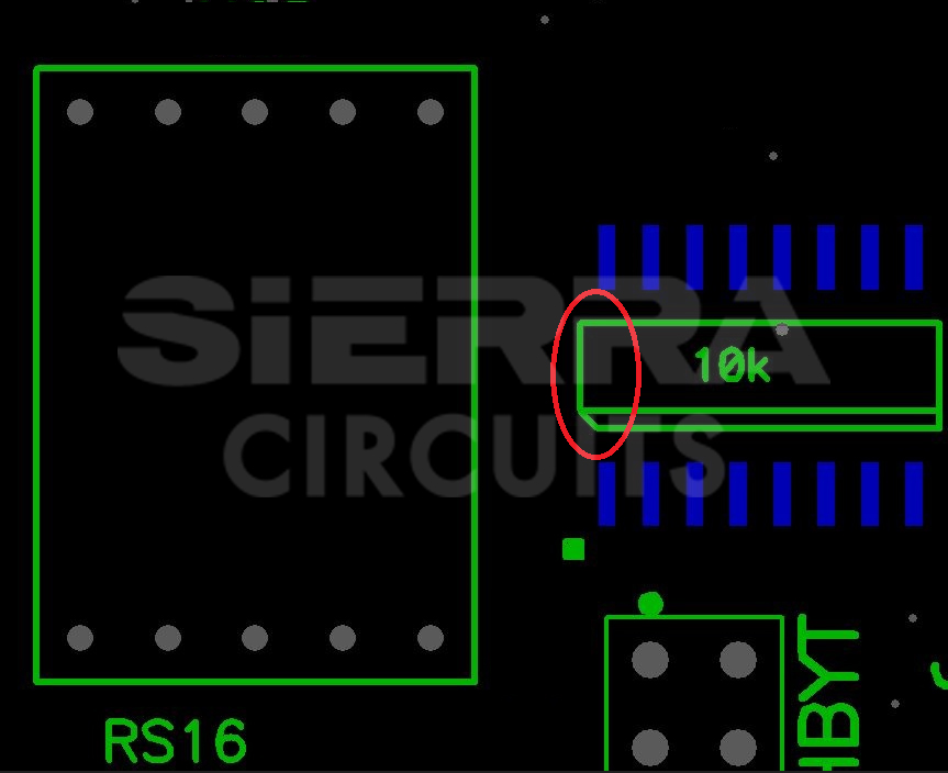
| ERA-8ARB103V | SMT resistor of 10KΩ |
| 08051A220J4T2A | 22pF SMT capacitor |
| 49BV1614-12TC | 1 Mb flash memory |
| 08055E104MAT050M | SMT ceramic capacitor |
| CPP-C4LTBP-30.000MHz | Programmable oscillator with 30 MHz frequency |
| MP-49-3.6864 MHZ | Dual N-channel MOSFET |
| SC28L92A1B-S | Asynchronous transceiver |
Component shortage
Component sourcing is one of the vital factors to consider for a smooth assembly process. Board production may be delayed due to component shortages. We had to ask our customer to share the alternative parts and footprints of the components enlisted below.
| Components' MPN | Part Specifications |
|---|---|
| T491C106K020AS | Molded, tantalum, SMT capacitor |
| MP037B | Through-hole crystal |
| ILD217T | Optocoupler transistor |
| TL28L92IFR | Dual asynchronous transceiver |
| SN74HC273PW | Octal D-type flipflop |
Obsolete parts in the BOM
When you review your material list, you need to identify outdated components and replace them with available ones. In this design, the embedded SMT digital signal processor (DSP), ADSP21065LKS-240, was obsolete. Later, the customer had to consign this part to us.
Key takeaways
- Verify the footprints with the respective components’ datasheet to ensure the right pad sizes, spacing between components, and board edge clearance.
- Include the correct MPN for the components in your BOM.
- Share the component datasheets with your manufacturer.
- Provide accurate pad, polarity, and pin designators.
- Always adhere to kitting guidelines while supplying parts to your CM.
At Sierra Circuits, we fabricate the highest quality circuit boards by realizing all the DFM and DFA standards. If there are any discrepancies in the design data, we intimate you and rectify the errors.
Please let us know in the comments section if you require any assistance to eliminate footprint and BOM errors in your design. Our engineers will try to resolve your queries.
Visit our PCB assembly page to learn more about our capabilities.
About Poulomi Ghosh : Poulomi is a microwave engineer specializing in EMI, EMC, RF, and high-speed electronics. As a senior technical writer at Sierra Circuits, she creates advanced engineering articles and webinars for hardware engineers and PCB designers.