


Contents

On-demand webinar
How Good is My Shield? An Introduction to Transfer Impedance and Shielding Effectiveness
by Karen Burnham
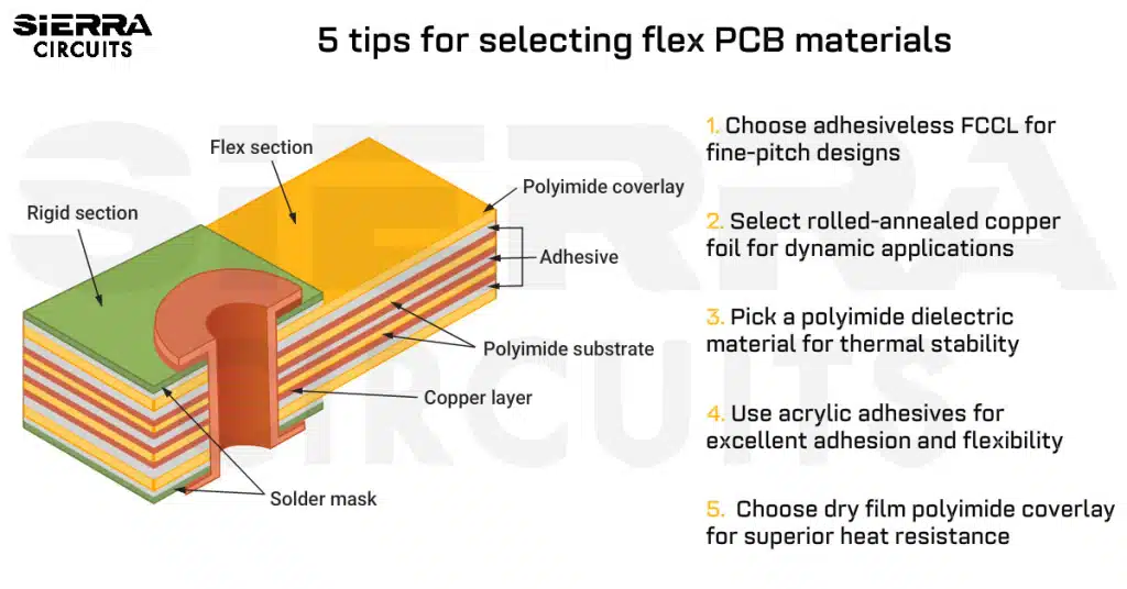
When selecting flex PCB materials, you need to consider the application type (dynamic or static), stiffener requirements, and routing needs.
For instance, choose adhesiveless copper-clad laminate for fine-pitch designs to ensure dimensional stability and good heat resistance. Likewise, use rolled annealed (RA) copper for dynamic applications, and select FR4 or polyimide stiffener when your assembly needs added mechanical strength.
Highlights:
- Use adhesiveless laminates (e.g., DuPont Pyralux AP, Panasonic Felios FX) for high-density flex circuits.
- Choose RA copper foil for dynamic applications, and align the rolling direction with the primary bend axis.
- Select polyimide (PI) film as the primary dielectric for high-temperature flex boards.
- Use PTFE or LCP dielectric films for RF, microwave, and high-speed circuits.
- Choose dry film polyimide coverlay for excellent heat resistance.
In this article, you’ll learn how flex laminates are classified, the key materials used in flex printed circuit (FPC) construction, and practical tips to select the right materials for your designs.
What materials are used to fabricate flex PCBs?
Copper foil, dielectric material, adhesive, coverlay, and stiffener are the core materials used to manufacture FPCs. In adhesive-based constructions, an adhesive bonds the copper foil to the substrate; adhesiveless stack-ups eliminate this layer.

Let’s take a closer look at each of these flex circuit board materials:
1. Copper foil
Copper foil is the conductive layer that forms circuit traces through etching. FPCs mostly use rolled annealed (RA) copper, as its elongated grain structure can withstand repeated bending without cracking. In contrast, rigid PCBs and some static flex boards use electrodeposited copper, which is more brittle and suited only for static applications.

After Cu production, the foil undergoes treatment to improve adhesion and oxidation resistance:
- One side is roughened to enhance peel strength.
- The other side receives an anti-oxidation treatment to maintain surface stability.
The thickness of copper foil is often expressed in terms of its weight per square foot. For instance, 1 oz copper means that 1 ounce (28.35 g) of copper spread uniformly over 1 square foot has a thickness of approximately 1.37 mil (≈1.4 mil).
| Standard Cu thickness (in oz) | Approx. mil | Micrometers (µm) |
|---|---|---|
| 0.5 | 0.7 | 18 |
| 1.0 | 1.4 | 35 |
| 2.0 | 2.8 | 70 |
Rolled copper has better ductility and bending endurance (elongation 20-45%) than electrolytic copper (4-40%). The rolling direction of the copper foil should align with the primary bending axis of the flexible circuit to prevent cracking and extend bend life.
Pick RA copper if you’re working on a dynamic application.
For more on flex layout, download our Flex PCB Design Guide.

Flex PCB Design Guide
10 Chapters - 39 Pages - 45 Minute ReadWhat's Inside:
- Calculating the bend radius
- Annular ring and via specifications
- Build your flex stack-up
- Controlled impedance for flex
- The fab and drawing requirements
Download Now
2. Dielectric material
Flex PCB substrate provides mechanical support and electrical insulation. Its performance depends on heat resistance, mechanical strength, and flexibility.
Three common dielectric film types used in FPCs are:
- Polyimide (PI): The most widely used dielectric film, as it strikes the right balance among flexibility, solderability, and dimensional stability. Example: Kapton (DuPont).

Stress is applied to the adhesive-based flex stack-up.
The graph below shows a stress vs. strain (elongation) plot for Kapton HN at different temperatures (230°C, 100°C, 200°C). As the temperature increases, Kapton requires less stress to achieve the same elongation. In other words, it becomes softer/more compliant at higher temperatures. But it still maintains predictable mechanical behavior across all temperatures.

The graph below shows how Kapton HN’s elongation changes over time under constant stress at different temperatures (26°C and 100°C). This indicates excellent dimensional stability, making it reliable for flex circuits that experience long-term mechanical stress.

- Polyester (PET): Favored when high heat resistance is not required; offers better moisture resistance and optical transparency than PI but loses strength above 80°C.
- Polytetrafluoroethylene (PTFE): Provides the best electrical insulation and environmental resistance; widely used in high-frequency flexible copper-clad laminates.
Flex dielectric comparison: Polyimide vs. Polyester vs. PTFE
| Parameters | Polyimide (PI) | Polyester (PET) | Polytetrafluoroethylene (PTFE) |
|---|---|---|---|
| Heat resistance | Excellent; withstands reflow temperatures of up to 260°C | Fair; degrades above 80°C | Exceptional; stable between 200°C–260°C; melts at 327°C |
| Flexibility | High | High | Moderate |
| Mechanical strength | Excellent | Good; decreases at high temperature | Good; softer than PI |
| Dimensional stability | Good | Good | Excellent |
| Moisture absorption | Low | Low | Extremely low |
| Electrical insulation | Good | Moderate | Excellent |
| Solderability | Excellent | Poor | Excellent |
| Chemical resistance | Good | Moderate | Excellent |
| Flame retardancy | Good | Poor | Excellent (UL94 V-0) |
| Transparency | Amber/opaque | Clear/colorless | Translucent white |
| Cost | High | Low | Very high |
| Applications | Most FPCs, aerospace, and displays | Low-cost, low-temp FPCs | High-frequency, RF, aerospace |
Besides PI, PET, and PTFE, newer films such as polyethylene naphthalate (PEN) and liquid crystal polymer (LCP) are gaining popularity.
- PEN offers better dimensional stability and moisture resistance than PET but lower heat resistance than PI, ideal for mid-range cost applications.
- LCP provides ultra-low moisture absorption (<0.05%), high-frequency stability, and excellent dimensional control, making it suitable for RF, microwave, and high-speed signal flex circuits.
To meet RoHS and WEEE environmental standards, modern FCCLs and coverlays are formulated without brominated flame retardants. Halogen-free PCB materials and epoxy systems reduce toxic emissions during recycling and are now standard in high-end FPC manufacturing.

3. Adhesive
The adhesive layer bonds the copper foil to the base film or bonds multiple film layers together, such as the coverlay. The right adhesive ensures strong bonding and flexibility.
In flex boards, the adhesive performance directly impacts:
- Flexibility and bend life
- Heat and chemical resistance
- Lamination quality and yield
- Long-term reliability under reflow or environmental stress
Common adhesive types include acrylic and epoxy. They are available in different thicknesses, including 0.5 mil, 1.0 mil, and 2.0 mil. A third type, butyral phenolic, is occasionally used for specialized high-flexibility or insulation applications.
Comparison of FPC adhesive types: Acrylic vs. Epoxy vs. Butyral phenolic adhesives
| Parameters | Acrylic | Epoxy (modified) | Butyral phenolic |
|---|---|---|---|
| Strengths |
|
|
|
| Limitations |
|
|
|
| Best suited for | High-temperature FPCs and coverlays | General-purpose or single-layer FPCs | Specialized high-flexibility or high-insulation applications |
Sierra Circuits fabricates and assembles high-performance flex PCBs engineered to withstand harsh environments and support dynamic applications.
Check out flex PCB capabilities to learn more.
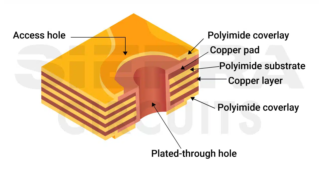
4. Coverlay (protective film)
Coverlay is an insulating layer used to protect copper traces on FPCs.

Two main coverlay types include:
- Dry film: Polyimide film laminated and pre-cut to expose pads.
- Photosensitive film: Photolithographically developed after UV exposure, available in dry-film and liquid screen-printed forms.
Common coverlay thicknesses include 0.5 mil, 1 mil, 1.4 mil, 2 mil, and 5 mil. Cost-sensitive designs may replace coverlay with solder resist ink.
Comparison of FPC protective film types
| Parameters | Dry film (cover film) | Photosensitive dry film | Photosensitive liquid screen-printed | Solder resist coating |
|---|---|---|---|---|
| Structure | Polyimide film laminated to the circuit surface (usually without adhesive pressing) | Photosensitive coverlay laminated, then exposed and developed to open solder pads | Liquid polyimide or photoimageable solder resist is applied through screen printing and then cured | Liquid solder resist |
| Strengths |
|
|
|
|
| Limitations |
|
|
|
|
| Best suited for |
|
|
|
|
5. Stiffener
Circuit board stiffener is a rigid material applied to specific areas of a flexible printed circuit to provide mechanical support, reinforce component mounting zones, and aid in connector insertion.
They ensure flatness, strength, and dimensional stability in areas that experience pressure or require soldering.

Common flex PCB stiffener materials include PI, PET, FR4, aluminum, and stainless steel.
Consider these parameters before selecting a stiffener:
- Operating temperature and reflow requirements
- Mechanical rigidity is needed for connectors or components
- Adhesive compatibility (thermosetting vs. PSA)
- Weight and cost constraints
- Heat dissipation needs
FPCs requiring reflow soldering must use PI, FR4, aluminium, or stainless steel stiffeners, laminated with thermosetting adhesive or pressure-sensitive adhesive.
For non-soldering applications, PET or PI can be used with standard PSAs to reduce cost.
Comparison of common flex PCB stiffener materials
| Parameters | Polyimide (PI) | Polyester (PET) | Glass epoxy (FR4) | Aluminum sheet | Stainless steel sheet | Paper phenolic board |
|---|---|---|---|---|---|---|
| Typical thickness range | 0.0125-0.125 mm | 0.025-0.25 mm | 0.6-2.4 mm | No fixed restriction | No fixed restriction | 0.6-2.4 mm |
| Heat resistance | Excellent (up to 130°C) | Poor (not suitable for soldering) | Good (up to 110°C) | Excellent (up to 130°C) | Excellent (up to 130°C) | Limited (≈70°C) |
| Mechanical strength | Moderate | Low | High | Very high | Very high | High |
| Adhesive compatibility | Compatible with thermosetting adhesive and PSA | Compatible with PSA | Works with thermosetting adhesive | Requires thermosetting adhesive | Requires thermosetting adhesive | Not compatible with thermosetting adhesive |
| Flammability rating (UL94) | 94V-0 | No UL rating | 94V-0 | 94V-0 | 94V-0 | 94V-0 |
| Advantages |
|
|
|
|
|
|
| Limitations |
|
|
|
|
|
|
| Use cases |
|
|
|
|
|
|
Download the PCB Material Design Guide to learn how to pick the right laminates.

PCB Material Design Guide
9 Chapters - 30 Pages - 40 Minute ReadWhat's Inside:
- Basic properties of the dielectric material to be considered
- Signal loss in PCB substrates
- Copper foil selection
- Key considerations for choosing PCB materials
Download Now
The choice of adhesive affects the reliability and processing method of stiffeners. The table below compares pressure-sensitive and thermosetting adhesives:
| Parameters | Pressure-sensitive adhesive (PSA) | Thermosetting adhesive |
|---|---|---|
| Thickness | 20–100 µm | 25–50 µm |
| Bonding strength | Medium | High |
| Creep resistance | Low | Excellent |
| Chemical resistance | Low | High |
| Reflow resistance | Good (limited) | Excellent |
| Process productivity | High | Low |
| Material cost | Low | Low |
| Process cost | Low | High |
PSAs such as 3M 467MP, 3M 468MP, 3M F9460 & 3M F9469 are commonly used for attaching stiffeners. Thermosetting adhesives are chosen where stronger bonding or thermal resistance is required.
Pressure-sensitive adhesives are suitable for budget-friendly, non-reflow applications, while thermosetting adhesives are preferred for high-reliability or reflow-processed assemblies.
In addition to stiffeners, adhesive films are also used to bond flexible layers to rigid sections in rigid-flex PCBs or to laminate multiple flex layers. These bondply films are typically acrylic- or epoxy-based and provide high peel strength, controlled flow during lamination, and stable dielectric performance.
Bondply thickness is selected based on cavity depth, number of flex layers, and the required rigidity of the rigid-flex transition zone.
Common bondply materials include DuPont Pyralux FR Bondply and Arlon 49N.
To learn how to address reliability issues in rigid-flex designs, see air gap construction method in rigid-flex PCBs.
Once you understand the key flex circuit board materials, the next step is choosing the right flex copper-clad laminate configuration. FCCLs combine these base materials into ready-to-use laminates. Here’s how they are categorized:
How are flex copper-clad laminates classified?
FCCL (flex copper-clad laminates) can be categorized in two ways:
- How the copper foil is bonded to the base film
- The number of conductive layers
The first classification is based on how the copper foil is bonded to the flex PCB substrate.
| Parameters | Adhesive-based | Adhesiveless |
|---|---|---|
| Bonding method | Copper foil bonded to base film using an adhesive layer (epoxy or acrylic) | Copper foil is directly laminated to the base film using heat and pressure (no adhesive) |
| Material composition | PI or PET base film, adhesive layer, copper foil, and coverlay | Polyimide base film, directly bonded copper foil, and coverlay |
| Thermal expansion |
|
|
| Advantages |
|
|
| Applications |
|
|
| Examples |
|
|

Common adhesiveless FCCLs include DuPont Pyralux AP and Panasonic Felios FX.
A 2-layer FCCL is more expensive and requires tighter process control compared to a 3-layer adhesive-based FCCL. Adhesive-based laminates such as DuPont Pyralux FR are widely used in cost-sensitive flex PCB designs.
In addition to the bonding method, FCCLs can be classified by the number of conductive layers used in the flex PCB stack-up.
| Parameters | Single-layer | Double-layer | Multilayer |
|---|---|---|---|
| Structure | One copper foil laminated to a flexible base material and covered with a protective film | Two copper layers separated by a dielectric or an adhesive film | Three or more copper layers interconnected through vias and bonded together |
| Material composition | Polyimide or PET base film, adhesive or bonding film, copper foil, and coverlay | PI film, copper foils, dielectric film, and coverlay | Multiple PI layers, copper foils, adhesives, and coverlays |
| Advantages |
|
|
|
| Applications |
|
|
|
How to select the right flex PCB materials?
When choosing materials for FPCs, you need to consider bending requirements, thermal performance, and routing density. In this section, we’ll outline the best practices for choosing laminates, copper foils, adhesives, coverlays, and stiffeners.
1. Choose adhesiveless or adhesive-based FCCL depending on your layout and bend requirements
- Use adhesiveless FCCL (e.g., DuPont Pyralux AP or Panasonic Felios FX) for fine pitch or dynamic applications.
- Select adhesive-based FCCL (e.g., DuPont Pyralux FR) for standard designs.
2. Select rolled-annealed copper foil for dynamic applications
- Use rolled-annealed (RA) copper foil for dynamic bending because of its high ductility.
- Ensure the rolling direction aligns with the primary bend axis to increase bend life and prevent cracking.
- Choose copper thickness based on circuit needs (e.g., 0.5 oz, 1 oz, 2 oz) and consider peel strength and oxidation resistance.
3. Pick a dielectric material by considering thermal and electrical needs
- Use polyimide as the primary dielectric for most applications, especially where soldering, high temperatures, or mechanical stability are required.
- Choose PET only for low-temperature, cost-sensitive designs where optical transparency or moisture resistance is beneficial.
- Select PTFE for RF, microwave, or high-speed designs.
- Consider PEN for mid-range applications where dimensional stability and lower cost are priorities.
To learn how our engineers balance structural reliability and signal integrity, see case study: designing loose-leaf rigid-flex PCB stack-up for enhanced reliability.
4. Employ adhesives based on bond strength and flexibility
- Select acrylic adhesives when excellent adhesion, flexibility, and reflow compatibility are needed, such as in high-temperature multilayer FPCs.
- Use epoxy adhesives for general-purpose or single-layer flex circuits requiring balanced electrical and mechanical performance.
- Choose butyral phenolic adhesives only for specialized designs that require high flexibility and insulation but do not undergo soldering or reflow.
5. Use dry film or photosensitive coverlay to meet layout density requirements
- Pick dry film polyimide coverlays for standard or low-density designs needing strong mechanical and chemical resistance.
- Choose photosensitive coverlays for fine-pitch or high-density circuits requiring high patterning accuracy.
6. Opt for a stiffener that matches your assembly demands
- Choose PI or FR4 stiffeners when reflow soldering is involved or when strong mechanical support is required.
- Use PET stiffeners only for non-soldering areas in low-temperature applications.
- Consider aluminum or stainless-steel stiffeners where high rigidity or heat dissipation is required.
- Match stiffeners with suitable adhesives (PSA or thermosetting) based on reflow compatibility and bonding strength.
7. Consider flex PCB materials that adhere to environmental regulations
- Choose halogen-free PI and epoxy systems to meet RoHS and WEEE requirements and reduce toxic emissions.
- Ensure dielectric films and adhesives meet flame-retardancy standards such as UL94, where necessary.
When selecting flex PCB materials, you need the right combination of adhesiveless or adhesive FCCLs, rolled-annealed copper foils, high-performance dielectric films, compatible adhesives, coverlays, and stiffeners.
With the proper material stack-up, you can build efficient FPCs that withstand dynamic bending, high temperatures, and demanding operating environments without failure.
About the technical reviewer:
Roopa Tirumala is a Senior Engineering Manager with 28 years of experience in rigid, flex, and rigid-flex PCB manufacturing. She manages cross-functional engineering teams across the USA, Canada, and offshore offices. Roopa guides NPI projects, collaborates closely with R&D and manufacturing groups. She also supports junior engineers through structured training and technical guidance, strengthening engineering capability across the organization.
Have queries regarding your flexible PCB designs? Post them on our community, SierraConnect. Our design experts will answer them.

About Pooja Mitra : Pooja Mitra is an electronics and communication engineer. With an experience of over three years in the PCB industry, she creates industry-focused articles that help electrical and PCB layout engineers.


Thanks for you.. is Blind and buried via will in Flex PCB ?
Yes, see our flex capabilities: https://www.protoexpress.com/products/flex-and-rigid-flex-pcb/