


Contents

On-demand webinar
How Good is My Shield? An Introduction to Transfer Impedance and Shielding Effectiveness
by Karen Burnham
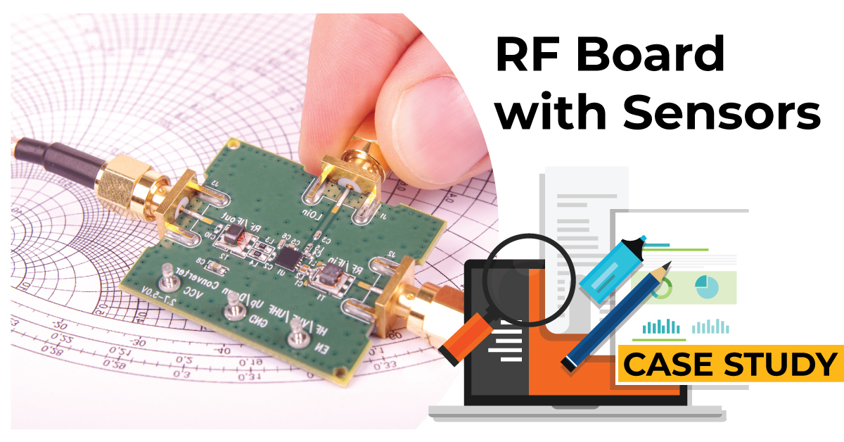
RF circuits work at high frequencies ranging from 500MHz to 2GHz. The design and fabrication of RF boards with sensors are quite challenging because they are prone to noise caused by electromagnetic interference (EMI) and radio frequency interference (RFI).
Sierra Circuits designed an RF PCB with three sensors and it required some special design considerations.
This RF board with sensors was primarily used in IoT applications. Here, we will talk about the specifications and the critical factors to consider while designing these kinds of boards.
Specifications of this RF board
- This design is a 4-layer board of dimensions 50 mm x 60 mm
- 2. 4 GHz is the operating frequency
- Includes an air quality sensor, a light sensor, and a humidity sensor.
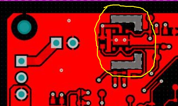
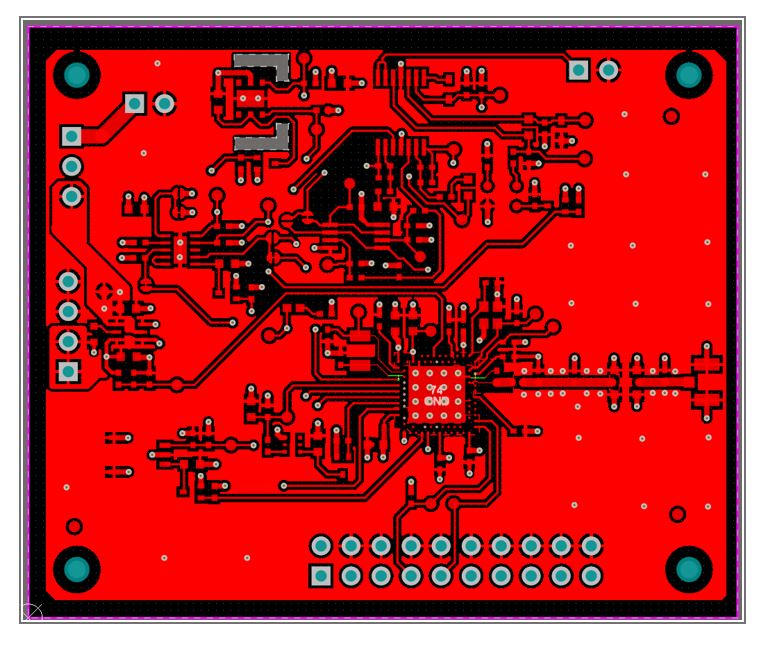
Anil Raiker, PCB Design Head at Sierra Circuits said, ” It is critical to isolate these sensors from the rest of the circuitry. If it isn’t isolated correctly, it will give erroneous results.
In the design, you can see L-shaped cut-out regions which are used for isolation of the sensors from the other signals.”
- The design has controlled impedance traces as per the RF circuitry standards. Controlled impedance is fundamentally matching the properties of the substrate material with the dimension and position of the traces.

RF & Microwave Design Guide
8 Chapters - 44 Pages - 60 Minute ReadWhat's Inside:
- Basics of RF and microwave board design
- Choosing RF materials
- Trace, grounding, via, and stack-up design
- Component selection and placement
- Testing and isolation requirements to avoid interference
Download Now
- In this board, the stack-up design includes coplanar waveguides to achieve greater isolation. In a coplanar structure, the conductor is placed between two ground planes. Via stitching is implemented in this case to connect the ground planes.

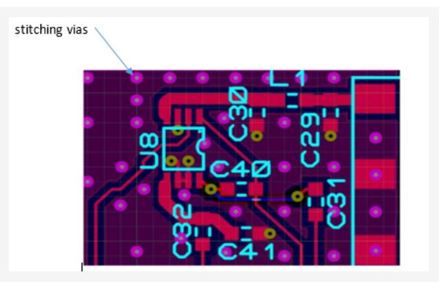
- Ground plane stitching for antenna and 50 ohms RF transmission line. Generally, RF PCBs involve transmission line design such as microstrip and stripline, or coplanar waveguide.
- This design required a thicker dielectric between trace and ground since the trace width is 30 mils.
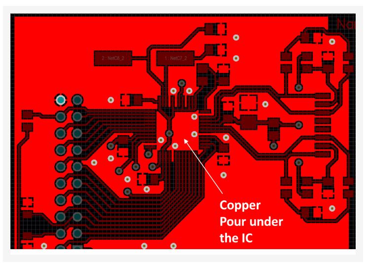
- This board comprises mixed analog and digital designs. Hence, ground pours/copper pours are designed to eliminate noise. This can be seen in the image below.
- Fine pitch BGA 0.5 mm package with via-in-pad design is included here.
See our article on How to design a PCB for 5G wireless applications to learn more about high-frequency PCB design.
Critical design considerations and solutions
When we asked about the critical design considerations for this design, Anil Raiker explained saying, “RF circuitry routing is performed considering the width and length of traces of 50 ohms. Apart from this, the isolation of the sensor signal from the other RF signal is crucial to avert the noise. In this board, the sensors are kept in the opposite direction and away from the antenna to mitigate the risk of interference.”
Anil described that sensor placements and associated component placement were accomplished as per the datasheets. He says it is necessary to isolate digital signals from analog signals and ensure that digital ground returns do not pass through the analog circuits.
For more RF board design tips, see antenna integration and RF design guidelines for 5G PCBs.
Sensors implemented in this RF PCB
According to Anil, the sensors in this board were placed in such a way that they never picked up any noise. As mentioned earlier, there are three sensors in this board – air quality, light, and humidity sensors.
Air quality sensor
Air quality sensors are used to determine air quality and pollution levels. Some of the features are:
- Monitor indoor and outdoor air quality
- Measure the densities of particular airborne substances
- Detect hazardous particulate matter

Light sensor
A light sensor is a photo-electric device that converts light energy (series of photons) into electrical energy. Light sensors implemented in:
- Smartphones
- Compact disc (CD) players
- Solar panels
- Automatic turn-on light system in vehicles
- Detection of sunlight in agriculture

Humidity sensor
Humidity sensors detect the moisture level and are the most sensitive components in a design. They are found in:
- Smartphones and tablets
- Weather forecasting
- Security systems
- Household appliances
- Medical instruments
Sierra Circuits analyzes the critical parts like isolating the RF section from the sensors. In the case of this board, the PCB design team identified the requirements like RF signals, operating frequency, material to be used, and controlled impedance traces. Along with this, the various sensor circuitry requirements for power and noise elimination were also considered.
The goal is to manufacture RF PCBs that maintain all specifications without compromising performance. Fabrication complexities never stop us from producing high-quality boards. The Sierra Circuits DFM team rigorously examines and ensures that all the boards match the manufacturing capabilities.
About Poulomi Ghosh : Poulomi is a microwave engineer specializing in EMI, EMC, RF, and high-speed electronics. As a senior technical writer at Sierra Circuits, she creates advanced engineering articles and webinars for hardware engineers and PCB designers.


