


Contents

On-demand webinar
How Good is My Shield? An Introduction to Transfer Impedance and Shielding Effectiveness
by Karen Burnham
A motor control PCB should be capable of protecting the motor circuit from overload (rise of current over a long period) which can cause electrical failure and hamper the functionality. This type of board manages the speed, torque, direction, and resulting output of the main device and also regulates the automatic start and stop. The high-current requirement is an important factor here.
Sierra Circuits designed a motor control board that supplies several amperes of current as per the motor requirement. This motor board has an excellent capacity to prevent excessive current and retain it within the specified maximum rating value. In this case study, we will discuss the specifications and critical measures that were taken while designing this board.
Specifications of this motor control board
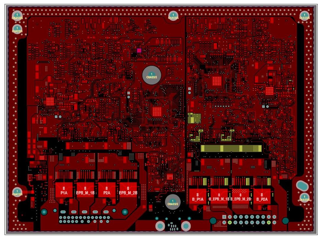
- This design comprises an 8-layered board with a dimension of 192 mm x 141 mm size.
- It incorporates the material FR-370 HR which offers maximum thermal performance and reliability.
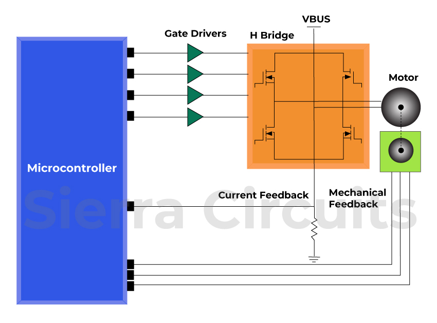
- The design involves a brushed DC motor controller. This kind of controller has efficient control over the torque and speed of the motor that can be attained directly by changing the PWM duty cycle and the current. The polarity and charges of the brushes determine the speed and direction of the motor.

- Over a thousand components are included in this board.
- 50 MHz operating frequency and ethernet of 100 Mb/S have been implemented. Ethernet is a conventional communication protocol in a network. It allows all the blocks connected to a particular network to receive, recognize, and process the information.
- This PCB required controlled impedance traces – 100 ohms differential and 50 ohms single-ended. The controlled impedance of the traces must be uniformly matched to achieve signal integrity.
- It is an IPC class-3 design. Class-3 boards undergo a thorough inspection to ensure high quality. They have a minimal tolerance limit, hence, choosing the right manufacturer matters a lot.

IPC Class 3 Design Guide
8 Chapters - 23 Pages - 35 Minute ReadWhat's Inside:
- IPC guidelines for manufacturing defects
- IPC standards for assembly processes
- Common differences between the classes
- IPC documents to set the level of acceptance criteria
Download Now
- The board operates on a very high current. The peak current is 30 amps, the average current is 20 amps in this case.
- CAN Bus interfacing is implemented in this design. CAN bus is a hardware interface involving serial binary interchange. It is used in complex, robust designs, majorly in the automotive and industrial sectors.
To get an insight into design considerations for automotive, read our blog on 10 automotive PCB design guidelines
Key design consideration
Anil. Raiker, the PCB design head at Sierra Circuits was happy to share the key design considerations of this board. He explained, “ The board requires current as high as 25 amps. Therefore, the high-current traces had to be split into different layers of the board. This specific routing technique is implemented to prevent the overload issue, and any damages caused by overload.”

When asked about the components, he said, ” There were quite a lot of components. More than thousands of components have been incorporated in multiple circuitries. Hence, placing these components was quite challenging. To prevent interference, we grouped them according to their functions using the same topologies. Since the locations of the input connectors were fixed, the component placement had to be done accordingly which was critical.”
Applications of motor control boards
The motor controllers are designed based on the required functionality. It can be used in any propulsion system like an electric bike, electric car, fuel pumps, and motorbikes.
- Electric cars and bikes: The motor controller is the brain of electric vehicles. All the electric components like throttle, motor, brake, forward and reverse control switches, and sensors are connected to the motor control that manages the energy flow, speed, and direction of the system.

- Multi-axis motion controller: It offers excellent service to automated systems with more than one axes. Each axis has one motor with one drive. All of them are connected and enclosed in a single compartment. Multi-axis drives are connected with multi-axis controllers to ensure better performance of the advanced motion control system.
- Robotic motion controller: It facilitates the flexible arms or wings to rotate, slide, move, and position themselves according to the assigned task.

- Servo motor: The servo motor is an electric motor that can precisely control the linear or angular position, acceleration, and velocity. It has an advanced motor control circuit to provide position feedback. It enables the servo motor to rotate or move with precision.
- High-speed tape recorder
- X-Y recorder
- Heavy-duty drives
- Optical position encoder in stepper motor
The design team of Sierra Circuits evaluates the schematic diagram of the circuit first. It helps analyze the circuit’s requirements of controlled impedance, routing density, PCB material, and operating frequency. Our DFM engineers examine all the vital specifications including high-current requirements and set up suitable fabrication rules. Sierra Circuits resolves the challenges of fabricating a complex board by establishing correct design constraints. We fulfill our customers’ expectations and deliver high-quality boards.
You can book a meeting with our experts or call us at +1 (800) 763-7503.

About Poulomi Ghosh : Poulomi is a microwave engineer specializing in EMI, EMC, RF, and high-speed electronics. As a senior technical writer at Sierra Circuits, she creates advanced engineering articles and webinars for hardware engineers and PCB designers.


