


Contents

On-demand webinar
How Good is My Shield? An Introduction to Transfer Impedance and Shielding Effectiveness
by Karen Burnham
Why should you care about the data output of the CAD tool (ODB++) after the PCB design is complete, provided that the design is sound and the description is thorough?
What are the differences between Gerbers (along with a drill file, netlist, BOM, board drawing, and readme text), ODB++, or any other file in the IPC-2581 format that you send to the manufacturer?
How your design is formatted determines how easily—and perhaps how successfully—the manufacturer can interpret what is intended to be built. Nearly 90% of the orders my company receives for fabrication and assembly are Gerber-based, even though it was more than 15 years ago that Valor introduced the ODB++ format for intelligently describing designs at the manufacturing level.
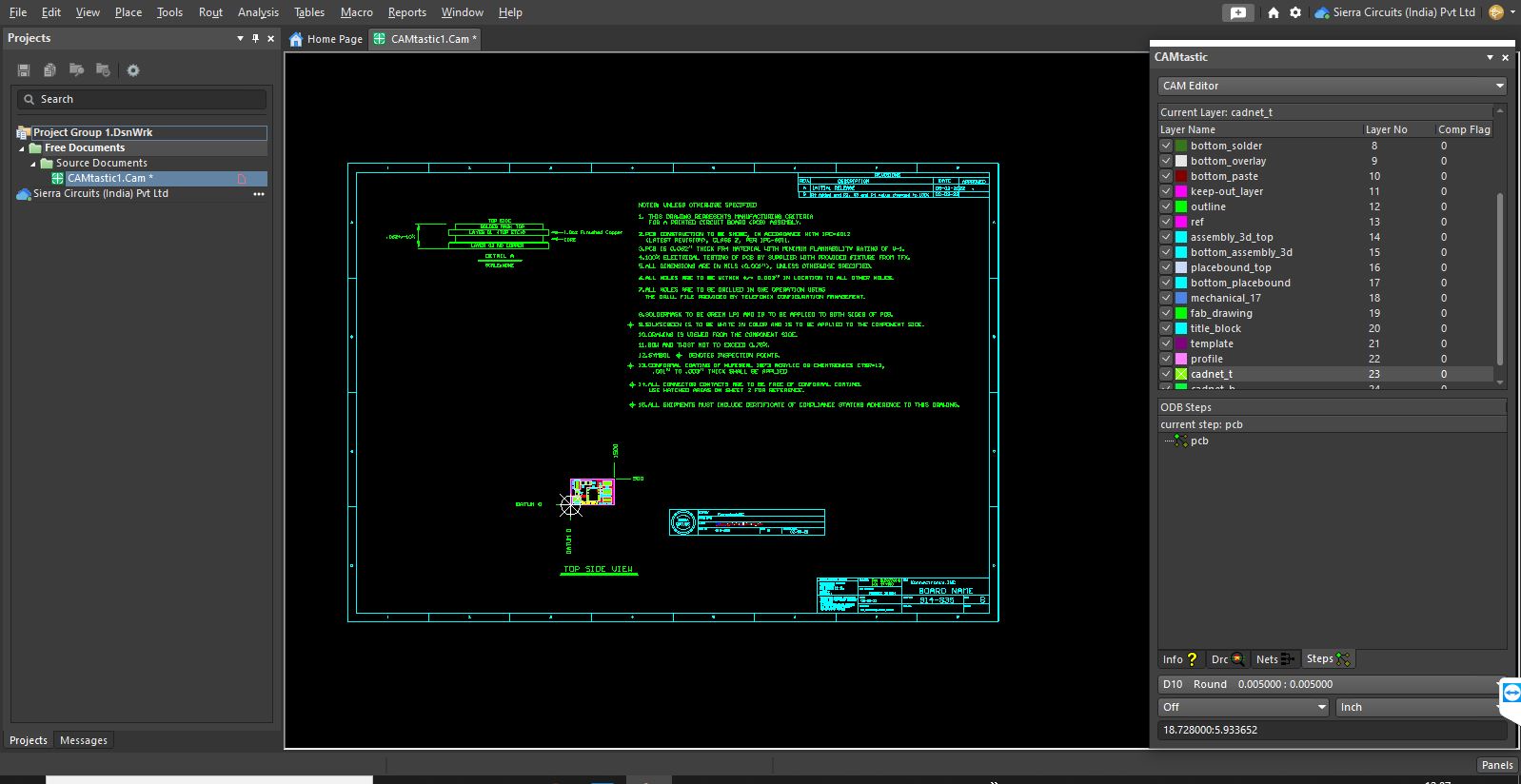
Each zipped ODB++ file, if complete, consolidates all the information needed for a board to be manufactured and assembled, and it can be directly loaded into the front-end CAM system.
What is ODB++?
Open database (ODB)++ is a CAD to CAM data exchange file format used in the design and manufacture of PCBs. It is a file that conveys all the required design information to a circuit board manufacturer. The latest file format includes ODB++ Design, ODB++ Process, and ODB++ Manufacturing . Thus the combination of these files helps to realize a design from a single concept to an entire manufactured board.

Design for Manufacturing Handbook
11 Chapters - 96 Pages - 90 Minute ReadWhat's Inside:
- Annular rings: avoid drill breakouts
- Vias: optimize your design
- Trace width and space: follow the best practices
- Solder mask and silkscreen: get the must-knows
Download Now
Why do manufacturers prefer ODB++ over Gerbers?
We would much rather receive ODB++ data, which our CAM tools can analyze in a fraction of the time required to convert and review Gerbers and their accompanying files. But of course, like other manufacturers, we are happy to accommodate our customers’ preferences.
Gerbers merely convey the outlines and locations of features layer by layer, whereas ODB++ data identifies the features and enables their sizes, shapes, and positions to be adjusted locally or globally to simplify manufacture and ensure good boards.
Gerbers are simple graphic representations that are hard to physically edit: A round pad is just a filled drawn circle completely independent of all other such circles. However, ODB++ defines pads as pads. For example, if necessary during CAM review, one, some, or all 10- mil pads can be enlarged to 12 mils.
Also read: How to Export Gerber and Production Files in Altium Designer
Data obtained from ODB++ files
Manufacturers do make slight adjustments in coordination with customers to preserve the integrity of designs. If there is insufficient spacing or inadequate pad size, the Valor system points it out. This could be resolved with a minor edit. The system then automatically checks the edit against the netlist to confirm that change has no effect elsewhere.
Each zipped ODB++ file consolidates all the information needed for a board to be manufactured. This data can be directly loaded into the front-end CAM system. The system will in turn output the programs to drive all the process equipment efficiently. When we receive a design described by Gerbers and the accompanying files, we convert these files so they can be loaded into our system for review. That takes time. Hence quick-turn manufacturers favor production formats that streamline transferring designs to fabrication.
To learn more about all the files required for board assembly, read our article on how to generate PCB assembly files.
ODB++ family
As mentioned earlier, this file format has been modified recently to make the design and manufacturing process easier. Now the complete package is called the ODB++ family and includes the following:
- ODB++ Design: These files carry all the design information required for a circuit board. It is created using any available EDA software. ODB++ Design file forms the basis to conduct DFA, DFM, and such related tests.

PCB Design for Assembly Handbook
6 Chapters - 50 Pages - 70 Minute ReadWhat's Inside:
- Recommended layout for components
- Common PCB assembly defects
- Factors that impact the cost of the PCB assembly, including:
- Component packages
- Board assembly volumes
Download Now
- ODB++ Process: The design data needs to be converted so that any machinery or production equipment can read it and perform the required action. Therefore, this file format is meant to transition the design data to any machine-readable format.
- ODB++ Manufacturing: These files are one step more advanced than the ODB++ Process files. ODB++ Manufacturing files provide necessary input for manufacturing floor events. They also form a communication channel for the interaction between smart industry software and machinery.
File structure
A Gerber file requires additional files to accompany it so that the manufacturer receives complete information. Thus, we need to send drill files, routing files, IPC-D-356, X-Y placement file, etc. along with Gerbers. In the case of ODB++, this is not required.
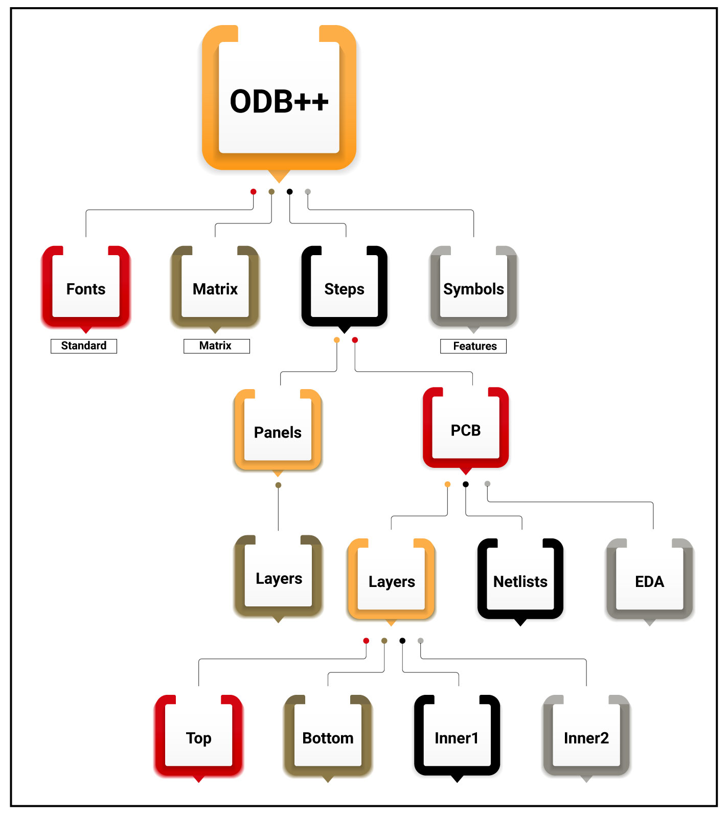
Even though ODB++ is sent as a single file, it is basically a framework that combines files or directories and zips them using gzip. It portrays a hierarchy that assists in the PCB design and manufacturing process.
IPC-2581
Like ODB++, the evolving IPC-2581 standard is an intelligent format for delivering all the data needed to automate PCB manufacturing, assembly, and testing. You can export the IPC-2581 file using EDA tools such as Cadence Allegro, Altium Designer, or KiCAD. Unlike ODB++, which is proprietary to Mentor Graphics since that company purchased Valor several years ago, IPC-2581 is open to implementation by anyone, with no license required.
Need help transitioning to ODB++ for smarter PCB design and manufacturing? Our engineering team can assist you with file format conversion, design-to-manufacturing data alignment, and CAM optimization to streamline your workflow.
You can book a meeting with our experts or call us at +1 (800) 763-7503.

Advantages of ODB++ files
They are widely imported by CAD and CAM vendors that it has become a virtual standard and no burdensome restrictions are imposed on the vendors licensing them. Mentor Graphics has designed it in such a manner that the use of other files that require conversion to ODB++ is not essential. This will reduce the errors that may occur during the conversion.
Sierra Circuits actively recommends the use of ODB++ because it saves time and uncertainty. IPC introduced the open 2581 standard many years ago and there are only a few customers who bring the design in that format. However, a truly open standard has chances to prevail.
Incidentally, regarding format uniformity, in the 1990s we compared the Gerber data from several EDA tools for a reference design. The outputs differed in accuracy and size of the data set. There is no guarantee that the ODB++ outputs by various platforms would exactly coincide either. Sierra Circuits has volunteered to build a reference design on behalf of the IPC-2581 Consortium when the CAM software is available for testing. We also intend to compare the results of a design output in Gerber, ODB++, and IPC-2581.
Read about IPC-2581 set to retire Gerber files across the board!
Let us have a look at the overall advantages of these files from all the information given above.
- A single file contains all design data for manufacturing, assembly, and circuit board testing.
- Reduced communication based delays between design and manufacturing.
- Supports automation during the manufacturing and assembly process.
- The most preferred standard chosen by most contract manufacturers (CM).
- The supply chain risks associated with data transmission errors are reduced.
- Compared to Gerbers, ODB++ portrays the difference between pads and conductors clearly.
- Fiducials, testing points, and all such parameters can be defined in an ODB++ file.
- Integrated DFM is supported in all layers.
Time is a crucial factor while designing and manufacturing circuit boards. The focus is to optimize and simplify the process as much as possible. Compared to conventional Gerbers, ODB++ files help to achieve this goal. If you have any queries related to this topic, please comment below.
Need assistance in designing your circuit board? Post your questions in the SierraConnect forum. We will be pleased to assist you!

About Amit Bahl : Amit Bahl, widely recognized as the PCB Guy, earned his Bachelor of Science in Engineering from UCLA. He is currently the Chief Revenue Officer at Sierra Circuits, where he continues to lead efforts to simplify the PCB design journey and support designers and engineers in creating high-quality boards.


