


Contents

On-demand webinar
How Good is My Shield? An Introduction to Transfer Impedance and Shielding Effectiveness
by Karen Burnham
In this tutorial, we will show you how to export Gerber and other production files in Altium Designer.
How to export Gerber files in Altium Designer
Open your design in Altium Designer and follow the steps below to generate the Gerber:
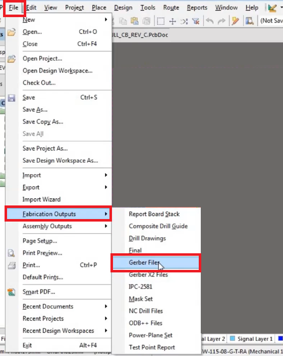
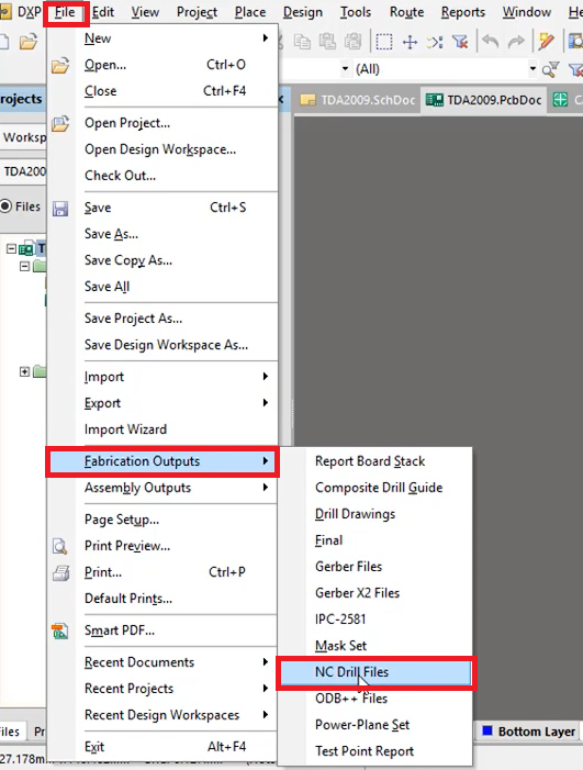
- Go to File > Fabrication Outputs > Gerber Files
- A window will popup
Required settings in the pop-up window
Perform the required settings in each tab of the pop-up window. The pop window: General tab
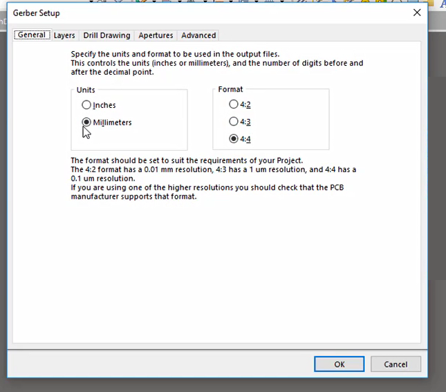
- On the General tab, set the Units of measurement (Millimeters) and select the Format for representing numbers in the output control information.
Layers tab:
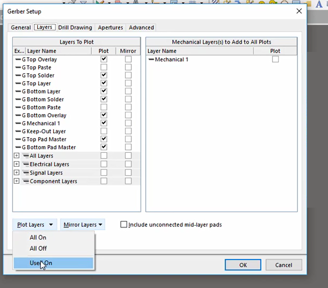
- On the layers tab, select all the layers for which you need to generate the Gerber by selecting the corresponding Plot checkbox of each layer, or you can select the Used On option from the Plot Layer dropdown which automatically selects all the used layers.
- Select the layer which you need to be mirrored from Mirror layers and add the Mechanical layer as well.
Drill Drawing tab:
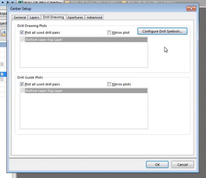
- On the drill drawing tab, you can assign the formation of layers with the drill drawings and the designations of the drill guide only if necessary or you can leave it to default settings.
Apertures tab:
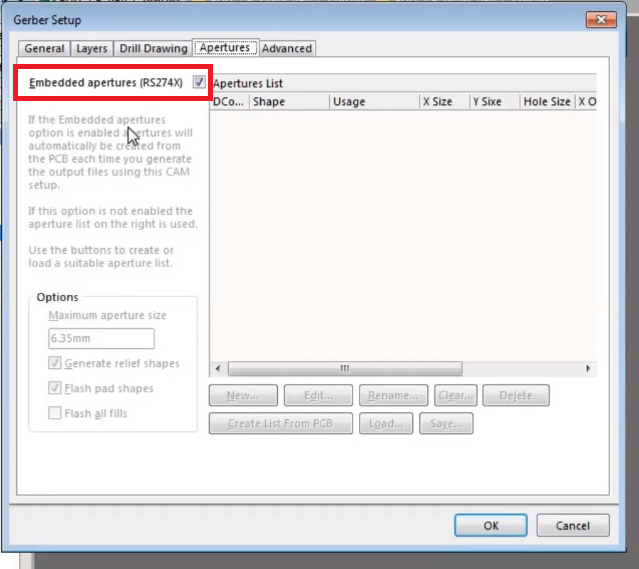
- On the apertures tab, you can activate (optional) the Embedded Apertures (RS274X) option. Selecting this option means that the output file will be generated in the RS274X format. Select only if your PCB manufacturer accepts RS274X format.
Advanced tab:
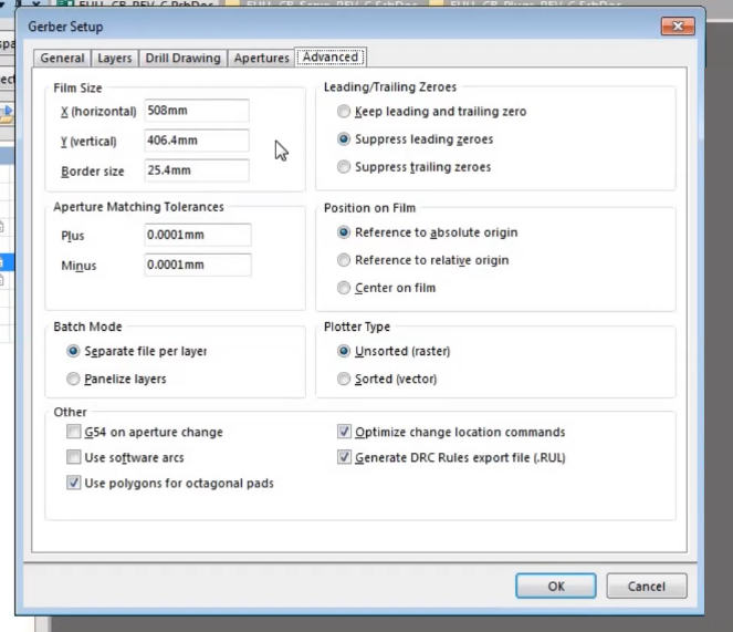
- On the Advanced tab, select the Separate file per layer option in the Batch Mode field, which allows generating a separate data file for each layer.
All the required settings in the Gerber setup popup is done. Next, click the OK button to generate the Gerber files. Your file will be generated at the selected location.
Examine these files for the common issues related to Gerber files like vectorized pads, obsolete file formats, etc. You can easily address and rectify those problems with CAD and DFM tools.
How to export the NC drill file in Altium Designer
Now that we’ve seen how to export Gerber files in Altium Designer, let’s go over exporting NC drill files.
- Go to file > Fabrication output > NC Drill Files
- A window will popup
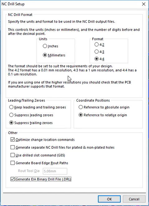
The popup window: NC Drill Setup:
Required settings in the pop-up window
- In the Units field and format field, choose the same options you set for the Gerber generation. The format should be agreed upon by your PCB manufacturer.
- From the rest of the settings, you can activate the option of Generate separate NC drill files for plated and non-plated holes for generating separate files for plated and non-plated holes.
- Do all other settings as per your manufacturer’s requirement.
Click the OK button to start generating the drill files.
How to export BOM in Altium Designer
To generate the BOM of your design, first, open the schematic of the design and follow the steps:
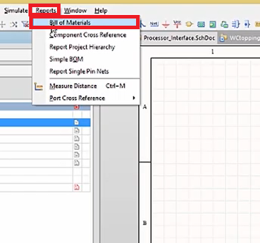
- Report > Bill of Materials
- A window will popup
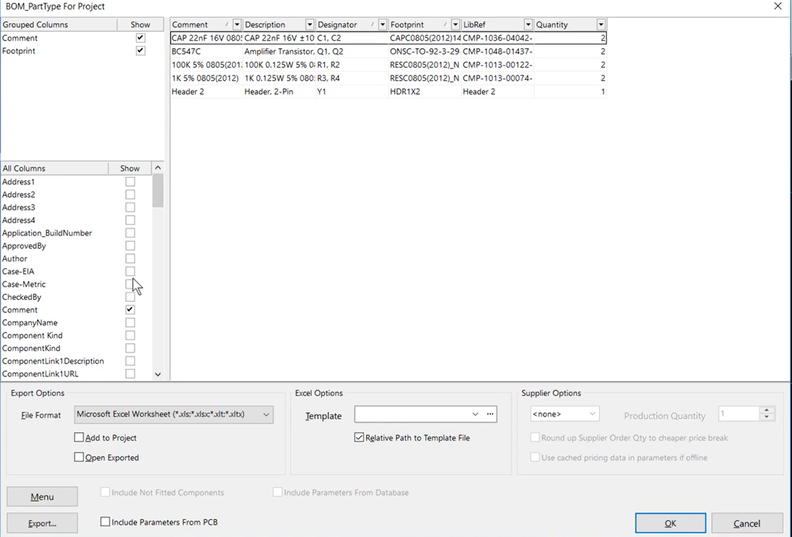
The pop-up window: BOM_PartType For Project
Required settings in the pop-up window
- The All Columns field contains a list of more than 90 items and control flags. You can include or exclude columns from the table by checking or unchecking the options. These can be component parameters, links to models, pointers to a library or database, document attributes, etc.
- A table will be generated in the popup so that you can verify your components listed in the table. The components in the table are grouped by type. The list is arranged alphabetically in ascending order of the component designation in the designator column.
- You can also rearrange the table by click and dragging the columns to the sides.
- In the lower field of the window, the export functions are grouped – Select a file format for BOM from the File format. Available file formats are listed below:
- CSV (Comma Delimited) (.csv)
- Microsoft Excel Worksheet (.xls)
- Tab Delimited Text (.txt)
- Web Page (.htm; .html)
- XML Spreadsheet (.xml).
- Also, choose a Template. You can choose a template from the available options or you can create your template.
Now click Export to save the BOM file.
How to export PDF file in Altium Designer
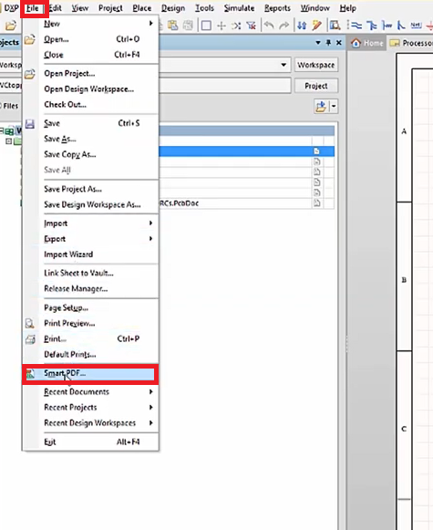
To generate a PDF of your design, first, open your design schematic and follow the steps below: File > SmartPDF > smartPDF wizard appears
The smart PDF wizard:
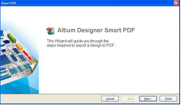
Click Next, Choose export target step:
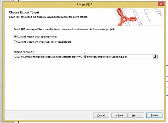
- Specify which objects are to be exported – choose the Current project with all the documents included in it, free documents, or choose the Current document.
- Also, choose a path to save the files.
Click Next, Choose project files:
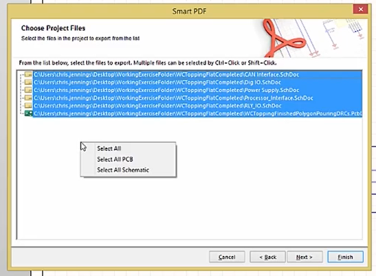
- Choose project files for which you need to generate PDF. To choose files, Right-click on the window and you will have options to choose. Click Next
Export Bill of Materials:
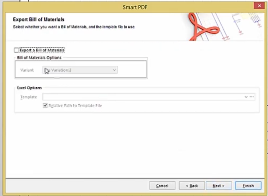
- You can generate your BOM from this tab also in the PDF format, select Export a Bill of Materials for that. Click Next.
Additional PDF Settings:
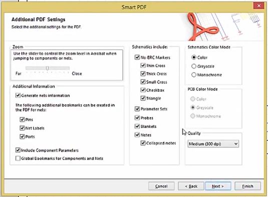
- In the additional setting, you have several options to customize your PDF. Do the required settings and click Next.
Structure Settings:
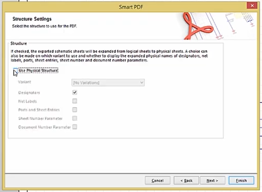
- In the structure settings, choose the ‘use physical structure’. Click next.
Final Steps:
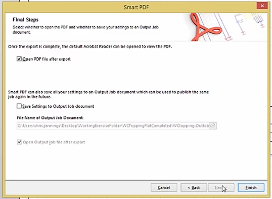
Last step for generating PDF files. Make sure to check the Save setting to output job document and Open output job file after export. Now click Finish. Your file will be generated at the selected output directory.
Export PDF 3D
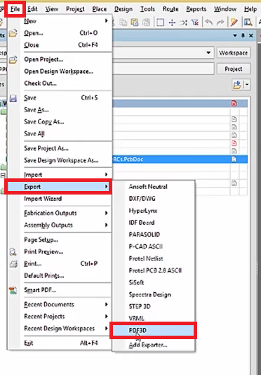
PDF 3D will show you the exact 3D image of the PCB design. Follow the steps to create 3D PDF: File > Export > PDF 3D
You have to select a location to save your PDF in the appearing window then Click save. Now, a new popup will appear:
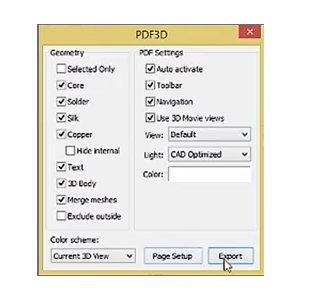
Perform the required settings in the popup window. Then click Export. You can open the PDF in any PDF viewer and view the 3D model of your design. Click and drag on the picture to see the object from different angles.
Need help exporting Gerber files from Altium Designer? Our engineering team can assist you with Gerber generation, drill file creation, and fabrication-ready output to ensure smooth manufacturing handoff.
You can book a meeting with our experts or call us at +1 (800) 763-7503.

How to export a netlist in Altium Designer
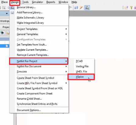
To create the netlist of your design, first, open the design in the schematic. Then follow the steps.
- Design > Netlist for project > Xspice
- A window will popup
The pop-up window: Analyses Setup
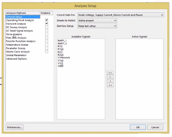
Click OK on the dialogue box. The netlist will be created and a message box will appear on the screen showing that your file is saved.
How to export ODB++ in Altium Designer
Some manufacturers also prefer ODB++ as an output design file. So let’s check how to export ODB++ in Altium. Follow the steps below:
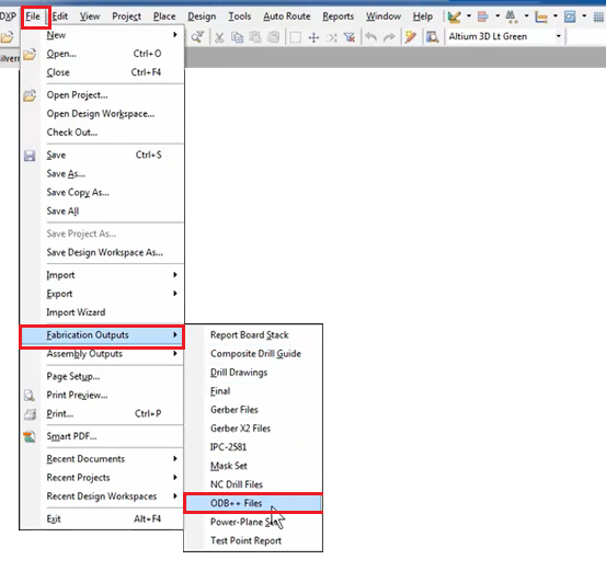
- File > Fabrication Outputs > ODB++
- A window will popup
The popup window: ODB++ Setup
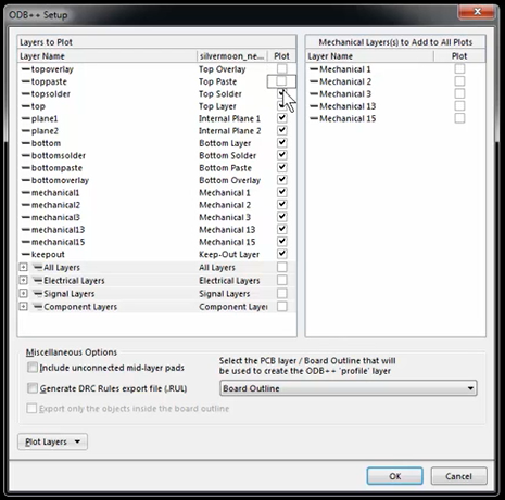
Required settings in the pop-up window
- The Layers to Plot field will contain a list of all the PCB layers of the currently open project. By checking the boxes in the Plot column make a list of the layers to be exported.
In the Miscellaneous Options field, setup the following:
- Include unconnected mid-layer pads – enable unconnected mid-layer pads
- Export DRC Rules export file (.RUL)
- Select the PCB layer / Board Outline that will be used to create the ODB ++ ‘profile’ layer as per your requirement.
This is how we export the gerber and other production files in the Altium designer. Now you can send these files to your manufacturer. Also, consult your manufacturer while choosing important parameters in the dialogue boxes.

High-Speed PCB Design Guide
8 Chapters - 115 Pages - 150 Minute ReadWhat's Inside:
- Explanations of signal integrity issues
- Understanding transmission lines and controlled impedance
- Selection process of high-speed PCB materials
- High-speed layout guidelines
Download Now


