Contents

On-demand webinar
How Good is My Shield? An Introduction to Transfer Impedance and Shielding Effectiveness
by Karen Burnham
High-speed PCB involves the transmission of signals with frequencies ranging from 50 MHz to as high as 3 GHz among various components of the board. The signal integrity is crucial here. An excellent high-speed board is one that integrates all the signals having a high frequency and routes them properly while maintaining signal integrity issues. Sierra Circuits designed a high-speed video board to incorporate ultra-modern technology. This design involves high video data and a distinctive board outline to meet the typical requirements of the product.
In this case study, we will focus on the specifications and critical factors that were considered while designing this high-speed video board. Before we dive right into the challenges, here’s a quick overview of the applications of video boards.
Applications of high-speed video boards
High-speed video boards attribute to diverse sectors due to their functionality. Some of them are:
Automobile industry
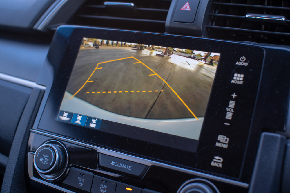
The modern automobile industry integrates a smooth driving experience with safety factors. This industry requires reliable, temperature-resistant, and small-sized PCBs. A high-speed video board is highly preferable to facilitate a navigation system, control system, and also the sensors used in the vehicles.
Healthcare
In the healthcare industry, high-speed video boards become the preferred choice in various advanced medical equipment, diagnostics, and monitoring devices. The miniaturized cameras embedded in these boards play a vital role in diagnostics.
Consumer electronics
Consumer electronic devices, starting from computers to smartphones, have huge implementations of high-speed video boards to support high-resolution.

Defense sector
High-speed video boards find immense applications in the military and aerospace sectors. They are part of strategic defense equipment like missiles. Generally, these designs are used in monitoring, navigation, control, and communication systems.
Specifications of this high-speed video PCB
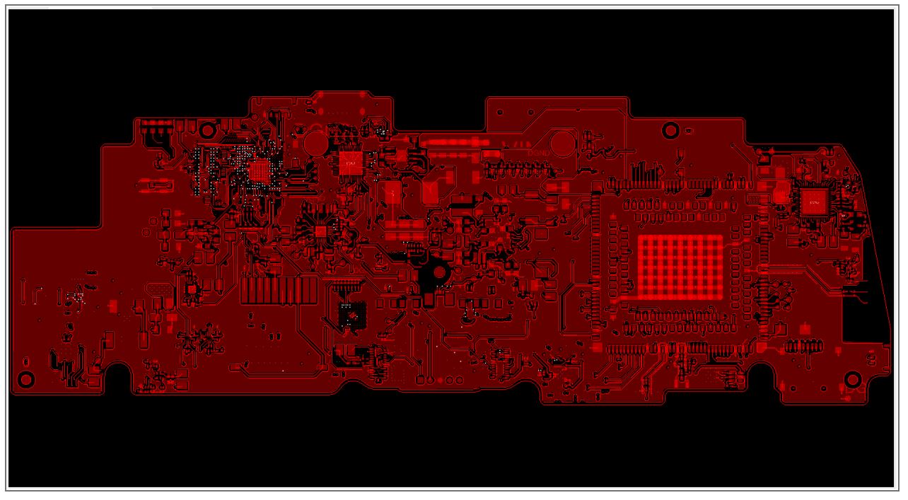
- The board that Sierra Circuits’ PCB design team worked on was a 10-layer board of 9” x 3” (228.6 x 76.2 mm) size with 4 power layers and 6 signal layers.
- It involves traces and spaces of around 4 mils.
- The memory interface implemented here is DDR3 with 800MHz. It has a high clock rate and large storage capacity.
- RF Bluetooth of 2.4 GHz was considered in this high-speed video board. This transmits signals over a shorter distance using radio waves of high quality.
- The board required controlled impedance traces – 100 Ohms differential and 50 Ohms single-ended. The design of controlled impedance is critical for maintaining signal integrity.
- The design comprises surface-mount packages:
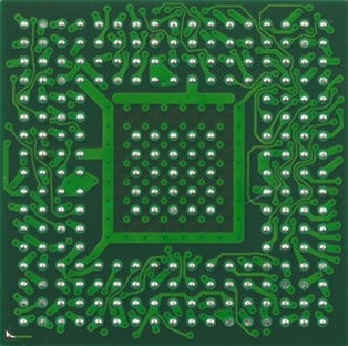
1. BGA 14 x 14 with 356 pins and 0.65 mm pitch
2. BGA 0.8 mm pitch
- As the data rate is very high, different communication interfaces were added to this design. They are :
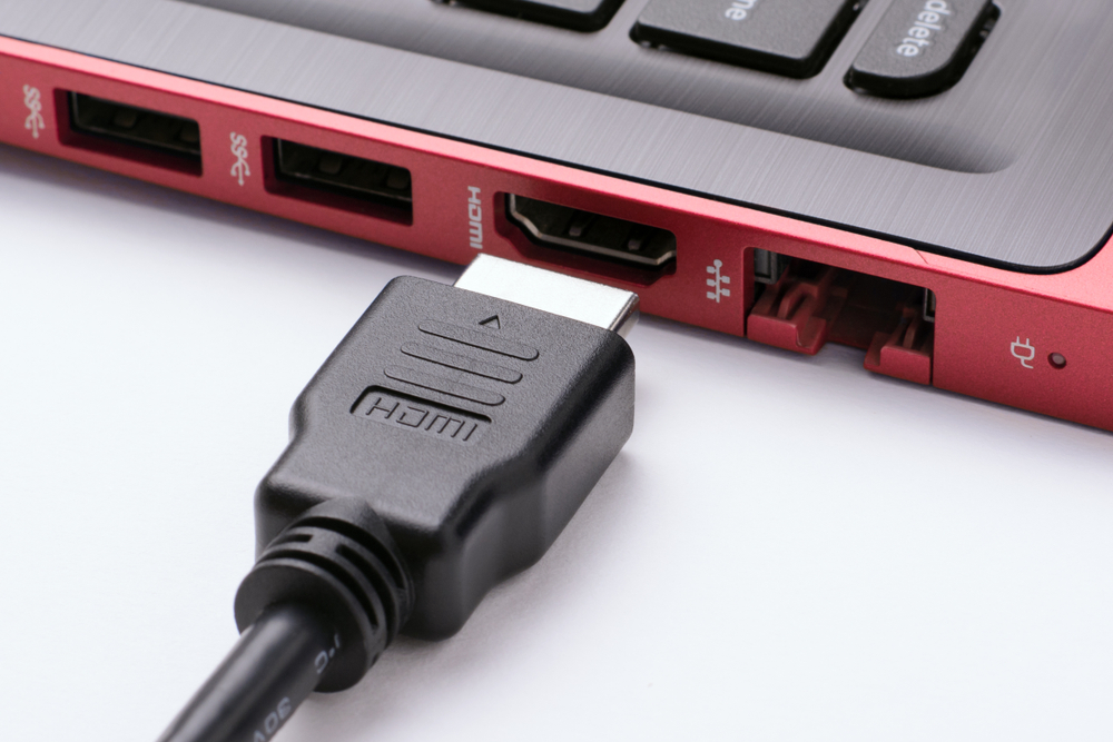
1. HDMI: High definition multimedia interface is used for transferring high-quality signals from one port to another at high data rates.
2.MIPI: MIPI stands for mobile industry process interface. It is a physical layer interfacing standard that defines interfaces among the physical layers, how devices communicate with each other, and how the signals are routed.
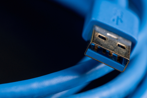
3.USB 3.0: USB 3.0 is the most popularly used computer interface worldwide with SuperSpeed specification.
4.SPI: The serial-parallel interface defines the routing between the traces of a board and the external device or component. It has a clock line, control line, and data lines.
5.I2C: I2C or inter-integrated circuit is a protocol that controls other devices’ transmission line behavior, and controlled impedance with one clock line and a data line.
Design challenges and critical constraints
When we asked about the design challenges, Anil Raiker, PCB design head at Sierra Circuits said, “Since it is a high-speed video board the data transfer rates are high. We had to use controlled impedance traces with length matching to around 50 mils to match the HDMI input signals.”

High-Speed PCB Design Guide
8 Chapters - 115 Pages - 150 Minute ReadWhat's Inside:
- Explanations of signal integrity issues
- Understanding transmission lines and controlled impedance
- Selection process of high-speed PCB materials
- High-speed layout guidelines
Download Now
He added that the shape of the board was irregular and was quite challenging since it had to fit into a particular form factor.
Anil further explained, “Since it was a dense board, the placement of components was another tough task. The connectors had to go into specific places and we couldn’t move them. Therefore, the components associated with the connectors had to be in fixed locations. Because of these reasons the routing and placement procedure turned out to be tougher than we thought.”
The PCB design team at Sierra Circuits has an expansive experience in different technologies including HDI, fine pitch BGA, blind and buried vias, and high-current boards. We analyze the requirements like the operating frequency, the PCB material to be used, and controlled impedance. We examine and decide if a circuit board requires a high-speed design and fix suitable design rules such that it is easily manufacturable. Ultimately, our motive is to fabricate a board that maintains all specifications and gives high performance.


