


Contents

On-demand webinar
How Good is My Shield? An Introduction to Transfer Impedance and Shielding Effectiveness
by Karen Burnham
Metal core PCBs are used where high amounts of heat are generated in the circuit, and the generated heat needs to be dissipated quickly to avoid component damage. These boards offer good thermal conductivity and dimensional stability.
An aluminum core can also reduce the overall board weight, making it suitable for compact and high-power designs.
The rapid development of the LED industry, especially in high-power LED lighting, has raised concerns about heat dissipation. These LEDs are usually mounted on PCBs and thus can create problems within the circuit.
Without the right technique, heat dissipation will hinder the performance of electronic devices that run on high power. The implementation of metal cores in these kinds of applications proves to solve this problem.
In this article, you’ll learn what a metal core PCB is, its types, appliactions and advantages.
Highlights:
- Metal core boards improve heat dissipation by transferring heat directly to a metal base.
- They are widely used in high-power LED, automotive, and power electronics.
- Aluminum cores improve the performance and are lightweight.
- Copper cores provide higher thermal performance but at a higher cost.
- MCPCB stack-ups must remain symmetrical to avoid warpage.
- Plated through-hole usage must be minimized to prevent electrical shorts.
What is a metal core PCB?
A metal core printed circuit board (MCPCB), also known as a thermal PCB, incorporates a metal material as its base instead of the traditional FR4. This improves the thermal stability of the board.
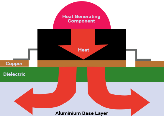
Some electronic components generate high heat when operating. The purpose of the metal is to divert this heat away from critical board components and towards less crucial areas, such as the metal heatsink backing or metallic core. Hence, these circuit boards are apt for thermal management.
In a multilayer MCPCB, the layers will be evenly distributed on each side of the metal core. For instance, in a 12-layer board, the metal core will be at the center with 6 layers on the top and 6 layers at the bottom.
MCPCBs are also referred to as insulated metallic substrates (IMS), insulated metal PCBs (IMPCB), thermal-clad PCBs, and metal-clad PCBs. In this article, we will be using the abbreviation MCPCB to avoid ambiguity.
The metal core boards are made up of thermal insulating layers, metal plates, and metal copper foil.

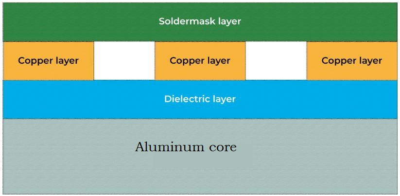
The basic structure of metal core boards comprises the following:
- Solder mask
- Circuit layer
- Copper layer – 1oz. to 6oz. (most commonly used 1oz. to 2oz.)
- Dielectric layer
- Metal core layer – heat sink or heat spreader
To learn more about effective heat dissipation techniques, see 12 thermal management techniques.
When should you choose an MCPCB?
A metal core PCB is ideal when conventional air cooling is insufficient to manage the heat generated by high-power components.
Accumulation of too much heat in printed circuit boards leads to malfunctions in the devices. Electronic devices that generate a considerable amount of heat cannot always be cooled using conventional fans.
Conductive cooling through metal core boards is an ideal option. In conductive cooling, the heat is transferred from one hot part to a cooler part by direct contact. This works well since heat constantly seeks to move to any object or medium that is cooler.
What are the applications of a metal core board?
MCPCBs are most widely found in LED lighting technologies. Some of the popular applications are:
- LED – Backlight unit, general lighting
- Automotive – motor control for Electric/Hybrid cars
- Motor drives
- Solid-state relays
- Power supply devices – voltage regulators, switching regulators, DC-DC Converters
- Solar panels, Photovoltaic Cells
- Motion control
What types of metal bases are used in MCPCBs?
An MCPCB commonly uses aluminum for cost-effective thermal management and copper for maximum heat dissipation.
1. Aluminum core
Aluminum printed circuit boards offer good heat dissipation and heat transferring ability. Since they are light in weight, aluminum core PCBs find their purpose in LED lighting, audio frequency apparatus, and communication electronic equipment.
Here, the thickness of the core ranges between 40 mils and 120 mils, with 40 mils and 60 mils being the most commonly used. Characteristics of the thermal circuit board with an aluminum substrate are as follows:
- Aluminum thickness: 2mm to 8mm
- Thermal conductivity: 5W/(mK) to 2.0W/(mK) (Watts per meter Kelvin)
- Peeling strength: >9lb/in
- Solder resistance: SF: 288℃, >180 sec.
- Breakdown voltage: >3000V
- Dielectric loss angle: 0.03
- Flammability: UL 94V-0
- Panel size: 18” x 24”
2. Copper core
The copper core boards feature better performance than aluminum. But customers generally choose aluminum since copper is relatively expensive. Also, copper cores are heavier and involve a tough machining process. Copper also corrodes more easily than aluminum.
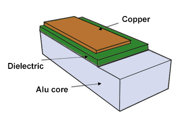
What is an aluminum printed board?
An aluminum circuit board features a standard dielectric material and an aluminum core, as shown in the image below. These boards have a thermal conductivity ranging from 1 W/mK to 9 W/mK and can withstand temperatures up to 400 °C.
4 types of aluminum PCBs
1. Single-layer
It is the simplest structure, with a single copper layer above the dielectric layer. You can only assemble surface-mount components on this type of board.
2. Double-layer with single-component mounting side
This has two layers of copper and prepreg, with one component mounting side (top).
3. Double-layer with dual-component mounting sides
The structure is very similar to a two-layer, dual-sided standard board. The only difference here is that there will be resin filling between the PTHs and the aluminum base.
4. 4-layer
A four-layer aluminum PCB has two copper layers and two prepreg layers on either side of the copper layers. The thermal conductivity of your Al board is indirectly proportional to the number of copper layers in your stack-up.
Which are the most commonly used base metals in MCPCBs?
Aluminum and copper are the most commonly used base metals in MCPCBs, chosen for their excellent thermal conductivity, mechanical strength, and suitability for heat-intensive applications.
The thermal conductivity of the metal core PCB dielectric material is measured in Watts per meter Kelvin (W/mK).
| Metal base material | Thermal conductivity (W/mK) | Coefficient of thermal expansion (µm/m-°C) | Features |
|---|---|---|---|
| Aluminum 5052 H32 | 138 | 25 | Al-Mg-Cr alloy; suitable for bending and mechanical forming; low cost |
| Aluminum 6061 T6 | 167 | 25 | Al-Mg-Si-Cu alloy; suitable for CNC machining and V-cut scoring; mid-range cost |
| Copper C110 | 386 | 17 | Pure copper; low CTE; very high thermal conductivity |
What are the advantages of a metal core circuit board?
An MCPCB offers superior heat dissipation, improved mechanical stability, higher power-handling capability, and enhanced reliability for high-temperature and high-power electronic applications.
These boards possess the ability to integrate a dielectric polymer layer with high thermal conductivity for lower thermal resistance.
- The higher the conductivity of the material, the faster the heat transfer.
- The metal boards can be etched to control heat flow away from components
- Boards with aluminum tend to be lighter in weight than ceramics.
- Metal substrates are long-lasting and are more conductive than epoxy products.
- Metals are non-toxic and recyclable.
- Implemented in high-vibration applications. The components don’t fall off since the core reduces the vibration.
How is a metal core board manufactured?
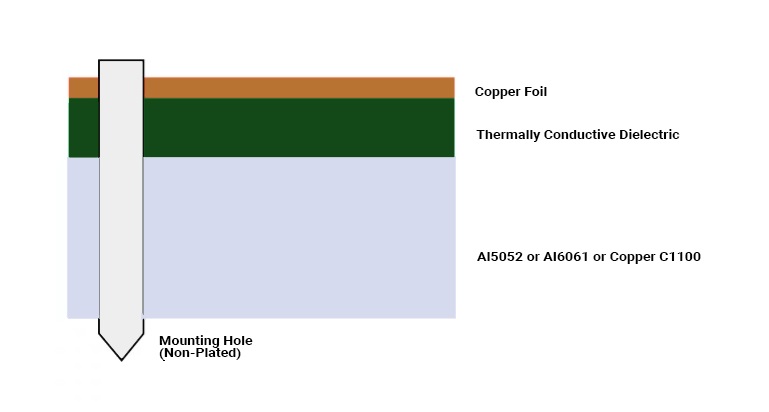
In an MCPCB manufacturing, the copper circuitry is bonded to a thermally conductive dielectric, which is then bonded to a metal base.
In a typical single-sided LED MCPCB, copper foil is bonded to a thermally conductive dielectric material layer. This dielectric layer is further bonded to a thicker metal, which can be either Aluminum 5052 (5052H32), Aluminum 6061 (6061T6), or Copper C1100.

Design for Manufacturing Handbook
11 Chapters - 96 Pages - 90 Minute ReadWhat's Inside:
- Annular rings: avoid drill breakouts
- Vias: optimize your design
- Trace width and space: follow the best practices
- Solder mask and silkscreen: get the must-knows
Download Now
Typical thicknesses of the dielectric layer and the metal core
The core is made up of a metal plate of a particular thickness that dissipates heat. The thickness is in the range of 30 mil to 125 mil. The copper foil thickness is around 1oz to 10oz.
The metal core or the metal backing plate is the thickest material in the board. The most frequently used thicknesses are 1mm, 1.5mm, and 3.2mm.
The metal layer offers rigidity, maintains the circuit flat, and provides sufficient thickness so that it’s compatible with the mounting hardware implemented on standard boards. The exposed metal plate side of the board isn’t coated with a surface finish or solder mask.
| Parameter | Specification |
|---|---|
| Copper thickness | 35 µm |
| Dielectric thickness | 100 µm |
| Dielectric thermal conductivity | 1 to 3 W/mK |
| Aluminum core thickness | 1.5 mm |
Thermally conductive prepreg
The prepreg electrically isolates the copper circuitry layer from the metal layer and assists in heat transfer between the two layers. The prepreg disperses the heat generated by the components to the base metal at the earliest.
The higher the thermal conductivity of this layer, the better the heat transfer. Also, the lower the thermal impedance better the heat transfer.
However, the higher the heat transfer rate associated with the prepreg, the higher the cost of it. The dielectric thickness also plays a role in heat transfer. Usually, the thickness ranges from 2 mils to 6 mils.

PCB Material Design Guide
9 Chapters - 30 Pages - 40 Minute ReadWhat's Inside:
- Basic properties of the dielectric material to be considered
- Signal loss in PCB substrates
- Copper foil selection
- Key considerations for choosing PCB materials
Download Now
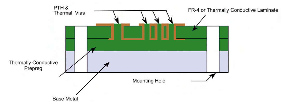
Plated through holes in MCPCB
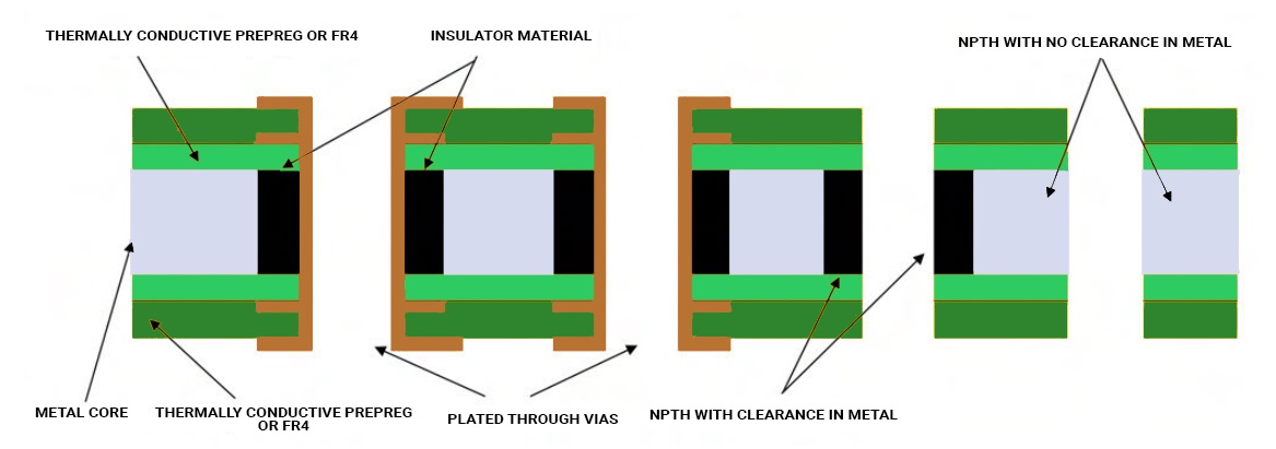
A major factor to keep in mind during the design process of an MCPCB is to minimize the use of plated through-hole components. Instead, implement SMT components. Since the bottom layer is a metal, PTH or NPTH with conductive component leads inserted to it will lead to a short.
If PTHs are implemented, then do remember to isolate the metal from the through-hole. To achieve this, the metal core is drilled approximately 40 mils to 50 mils larger than the plated through-hole. Later, these holes are filled with non-conductive epoxy filler and then pressed.
After pressing the metal core, the remaining filler compounds are removed from the surface. Following this, the boards are prepared for lamination with the inner layer cores. Right after lamination, the plated through holes are drilled, and the rest of the process follows as per the standard manufacturing protocol.
Unlike the standard LED PCBs, which require vias under the components for heat dissipation, the MCPCBs eliminate the necessity of these kinds of vias since the metal core performs the heat dissipation. Hence, this makes the work easier for the manufacturers as the drilling process is kept minimal.
After this process, if it’s a 1-layer MCPCB, the electroless plating process is bypassed and proceeds straight to circuit imaging. Hereafter, the metal core boards follow the same procedure that a standard FR4 board would follow.
Metal core circuit board stack-up
The stack-up should be symmetrical on either side of the metal core in a multilayer board. To elaborate, the number of layers on top of the core should be equal to the number of layers on the bottom.
Similar to any other standard printed circuit boards, the copper symmetry is also preferred. The symmetry is maintained to evade warpage issues.


Metal core PCB vs. FR4 PCB
Metal core boards transfer heat 8 to 9 times faster than FR4 PCBs. These metal core laminates keep the heat-generating components cooler by dissipating heat at a faster rate.
The dielectric material is kept as thin as possible so that it creates the shortest path from the heat source to the metal backing plate. This assists in quicker heat dissipation. The dielectric material thickness will usually be in the range of 0.003” to 0.006”.
| Parameters | MCPCBs | Standard FR4 PCBs |
|---|---|---|
| Conductivity | Higher thermal conductivity; typical values: 1 W/mK to 7 W/mK | Low thermal conductivity; typical values: 0.3 W/mK to 0.4 W/mK |
| Thickness | Thickness variations are limited; depends on the backing plate and the dielectric sheet thickness | Wide range of thickness options available |
| Thermal relief | Metal cores dissipate heat quickly; eliminates the need for thermal vias | Lower heat transfer rate; relies on thermal vias for heat dissipation |
| Plated through-hole | PTH not available in single-layer boards; components are surface-mounted | Supports plated through-hole (PTH) technology |
| Machining process | Similar to standard processes, except V-scoring uses diamond-coated saw blades to cut metal | Standard machining, including drilling, routing, V-scoring, countersink, and counterbore |
| Solder mask | Typically white for LED boards; applied only on the top layer | Available in multiple colors such as green, red, blue, and black |
| Rigidity | High rigidity; 2 to 4 times stiffer than FR4 or polyimide designs; better shock and vibration resistance | Lower rigidity compared to metal-core boards |
| Economy | Relatively more expensive than FR4 boards | More cost-effective |
Difference between heat sinks and heat spreaders
Since we are talking about heat dissipation a lot here, allow me to explain the difference between heat sinks and heat spreaders for you.
| Parameter | Heat sinks | Heat spreaders |
|---|---|---|
| Primary function | Dissipate heat directly into the surrounding air | Spread heat away from hot spots to a larger, cooler area |
| Cooling mechanism | Convection (natural or forced airflow) | Conduction to another surface |
| Surface structure | Fins or pins to increase surface area | Flat surface |
| Airflow requirement | Required (natural or fan-assisted) | Not required |
| Active components | Can be passive or active (with fans) | Always passive |
| Heat dissipation rate | Faster, especially with active cooling | Slower, indirect dissipation |
| Typical materials | Aluminum, copper | Copper, aluminum, graphite |
| Mechanical robustness | Less suitable for high shock and vibration | Ideal for shock- and vibration-prone environments |
| Environmental exposure | Works best in open or ventilated systems | Suitable for sealed or enclosed systems |
| Common applications | CPUs, GPUs, power transistors, switching devices | Sealed electronics, rugged systems, compact designs |
Here, the basic idea is to dissipate heat from the heat-generating components, like the processors, to the surrounding air medium.
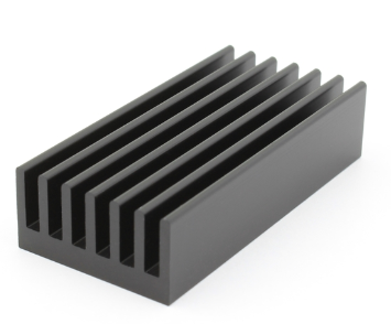
Heat sinks
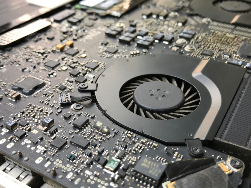
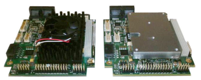
Heat sinks maximize the surface area and airflow to dissipate heat. The surface area is increased by implementing pins or fins on the surface, and the airflow is achieved by using built-in cooling fans. In some cases, heat sinks dissipate heat at a faster rate compared to heat spreaders.
Basically, there are two kinds of heat sinks: passive and active. The passive heat sinks have no moving parts, whereas the active ones do. When the volume of heat is too much to dissipate, then the active heat sinks are used. Here, the system is cooled by forcing air or other fluids through it.
Heat sinks are generally implemented in CPUs, GPUs, power transistors, and switching devices.
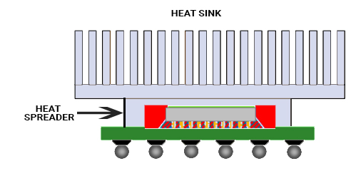
Heat spreaders
Unlike heat sinks, heat spreaders have a flat surface on the top. Instead of fans and pins, the heat spreaders are pressed directly against another large flat surface. The heat spreaders do not cool the region by forced air cooling or any other liquid fluid medium.
They transfer heat to a cooler area where the heat is dissipated safely away from the components. Heat spreaders are ideal for systems that operate under extreme shock and vibration. Also, they are used in systems that are sealed and isolated from the environment.
With the rising demand for printed circuit boards that are of high power and high component density, thermal management plays a crucial role in the reliability of these boards. The implementation of metal cores can greatly assist in thermal management.
Effective heat dissipation depends on the amount of heat generated by components, the enclosure, and the environment. Let us know in the comments section if you require any assistance in designing a metal core PCB.

About Rahul Shashikanth : Rahul Shashikanth is an electronics and communication engineer with over 8 years of experience in publishing technical articles on PCB design, manufacturing, and assembly. He is currently the content marketing manager at Sierra Circuits.


Start the discussion at sierraconnect.protoexpress.com