Contents
For an IC package to function as intended, the channel that connects it to the power supply should be reliable. One of the efficient ways to achieve this type of electrical connection is wire bonding.
In this article, we discuss the ways in which wire bonding is performed and the commonly used metals to achieve bonding.
What is wire bonding?
In microelectronics, wire bonding is an interconnection process that uses a thin wire, heat, pressure, and ultrasonic energy to create electrical interconnections. It is basically a welding process that involves two materials – wire and a pad– coming into close contact. Subsequently, electron sharing occurs, resulting in the formation of wire bonds.
Wire bonding mechanisms
As mentioned earlier, wire bonding is the process of attaching a bond wire with a bond pad. This process requires the application of force, temperature, and ultrasonic energy. According to the type of input energy, there are three joining methods for standard bonding.
Thermocompression (TC) bonding
Thermocompression bonding is a traditional method that uses a mechanical force and a high- temperature for bonding. It is commonly used for the gold (Au) wire to gold pad wedge-wedge bonding. Nowadays, it is not preferred due to its high-temperature requirements and long processing times.
To learn the ways to mitigate thermal issues in your PCBs, see 12 thermal management techniques to reduce PCB heating.
Ultrasonic (US) bonding
Ultrasonic bonding uses mechanical force and ultrasonic energy for the process. High-power electronic applications utilize this type for wedge-wedge bonding to attach the aluminum wire to aluminum or gold pads.
Thermosonic (TS) bonding
It is a fusion of thermocompression and ultrasonic bonding that forms ball-stitch bonding of gold wire. Thermosonic bonding is the most preferred interconnection method for packaging integrated circuit chips due to its reduced mechanical stress and processing time.
Materials used for wire bonding
The bonding material should provide good conductivity, bondability, hardness, and corrosion resistance. Following are the materials and their combinations:
Aluminum
It is suitable for thermosonic bonding. Alloyed aluminum wires are preferred due to their fine size and higher strength. Certain wire-pad material combinations commercially used are Al-Au, Al-Ni, etc. Pure aluminum is too soft to be drawn, so it is alloyed with 1% Si (silicon) or 1% Mg (magnesium) to provide a strengthening mechanism.
Copper
It is one of the best materials in semiconductor applications. Copper wires have a large diameter and can replace aluminum wire in high-current applications. It is used for fine wire ball bonding in the size range of 10 micrometers to 100 micrometers. The ball bonding must happen in an inert atmosphere as copper oxidizes readily.

Silver
Silver (Ag) wires have good thermal and electrical conductivity. The suitable combinations (wire-pad) are Ag-Au, Ag-Al, and Ag-SiC.
Gold
Pure gold wires with sufficient amounts of other elements are necessary for ball bonding. The widely used combinations are Au-Al, Au-Cu, Au-Pd, etc. Gold wire is used for thermocompression and thermosonic bonding. Surface finish and surface cleanliness are essential for strong bond formation and for preventing clogging of capillaries.
Types of wire bonding
It is classified into two main categories: ball and wedge bonding.
Ball bonding
It is the most common way to make electrical interconnections. The following image shows the ball bonding process.
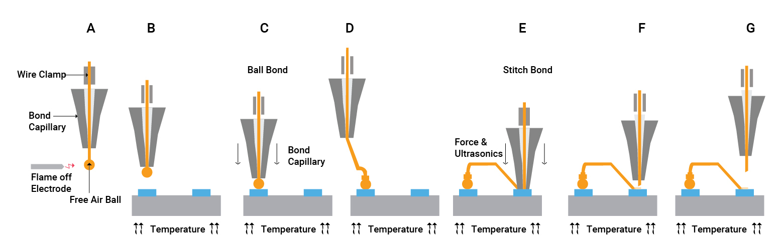
A thermosonic ball bond process uses a gold wire attached to gold or aluminum pads. The steps are as follows:
- A gold wire passes through a ceramic bond capillary (a needle-like tool). Then a high-voltage electric charge melts the wire, creating a gold sphere (free air ball, or FAB) at the end.
- Next, the free air ball forms at the tip of the capillary, and the tool moves sideways to a position above the required bond pad on the device which is placed on a heated surface.
- The tool presses the free air ball with a specified force against the pad. Ultrasonic energy creates a connection between the ball and the pad.
- Later, the tool moves towards the second bond pad where the stitch bond is produced.
- The wire is compressed between one side of the capillary tube and the pad.
- The applied force, ultrasonic, and heat energy form the connection between the wire and the pad.
- The wire is pulled apart with the tool by closing the wire clamp and pulling it straight up. It leaves the small tail of the wire from the end of the capillary, and the next cycle begins by applying a high-voltage electric charge to this tail.
To learn about gold wire ball bonding see, gold wire ball bonding against reflow.
Gold ball bumping
Gold ball bumping is similar to ball bonding and is used to establish gold-to-gold interconnections for flip-flop packages. The gold bumps form on a wafer level (a thin slice of semiconductor used in the fabrication of ICs).
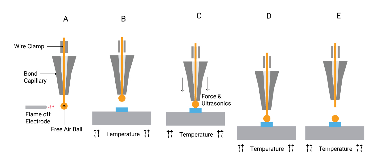
- An electrical flame-off melts the gold wire and forms a free-air ball.
- The free air ball attaches to a pad with a combination of force, ultrasonics, and temperature.
- The tool moves upwards to a certain height, instead of performing a stitch bond.
- Next, the wire is ripped off, and the tool moves upward.
- Usually, the wafer is diced, flipped, and then thermosonically bonded with gold pads.
The top surface of bumps is typically planarized in ball bumping. Ball bumping allows the stacking of multiple bumps. Ball bumping commonly involves planarizing the top surface of bumps. This method is known as coining, and it creates uniform bump heights and flat bump surfaces, resulting in an increased bond area.
Wedge bonding
It is ultrasonic bonding that utilizes aluminum wire bonded to aluminum or gold bond pads. Copper wedge bonding also forms strong bonds at room temperature. The process steps for the wedge bonding are as follows:
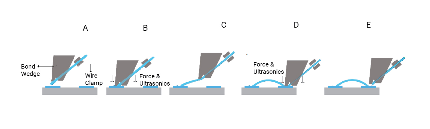
- Through the tool, a wire passes towards the wedge.
- The wire is then pressed against the bond pad with a predetermined force. A transducer then vibrates the wedge parallel to the substrate and along the wire axis using ultrasonic energy. It is in the range of 120−140 kHz.
- In the next step, the tool moves towards the second bond position. Similar to the first bond, the second bond is performed using force and ultrasonic energy.
- By pulling the tool backward, the wire clamp is closed, and the wire is torn off.
Aluminum wedge bonding
In aluminum wedge bonding, aluminum is only used as a wire-pad material. Here, a clamped aluminum wire comes in contact with the aluminum bond pad.
- With the application of ultrasonic energy, the wire is held down on the pad for a certain amount of time, which forms the first wedge bond between the wire and bond pad.
- The second bond forms by further application of ultrasonic energy to the wire. Later, the wire is broken off by being clamped.
Ultrasonic wedge bonding of aluminum wire enables the use of thin wire for fine-pitch applications and thick wire for high-power applications.

High-Speed PCB Design Guide
8 Chapters - 115 Pages - 150 Minute ReadWhat's Inside:
- Explanations of signal integrity issues
- Understanding transmission lines and controlled impedance
- Selection process of high-speed PCB materials
- High-speed layout guidelines
Download Now
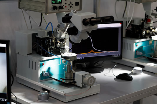
How does a wire bonder work?
A wire bonder is a machine that performs operations according to the process requirements.
There are several wire bonders available according to the type of bonding, modes, and operation. These machines can be manual, automatic, and semi-automatic as per the requirement.
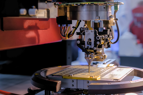
Wire bonding machine
A manual wire bonding machine is used for wedge bonding as well as ball bonding. It improves bonding rates, decreases bond pad pitch, and increases operational stability. There are many types of testing equipment used to monitor wire bonder performance.
The bonding location can be defined by the vision and positioning systems of the equipment. Automated equipment measures the bonding tool’s impedance in free air as the bond forms. These measurements can be used to boost the performance of the ultrasonic system and troubleshoot it. Another feature is the ability to change quickly from one product to another with minimal tooling and software changes. The user can write software programs for a wide range of items, store them on a disc, and use these programs for the process.
What is ribbon bonding?
Ribbon bonding is a way of interconnecting semiconductors using ribbons instead of round wires. It is quite popular in high-frequency electronic applications. It is a type of wedge bonding that employs ribbons over round wires.
There are several reasons behind using ribbon bonding.
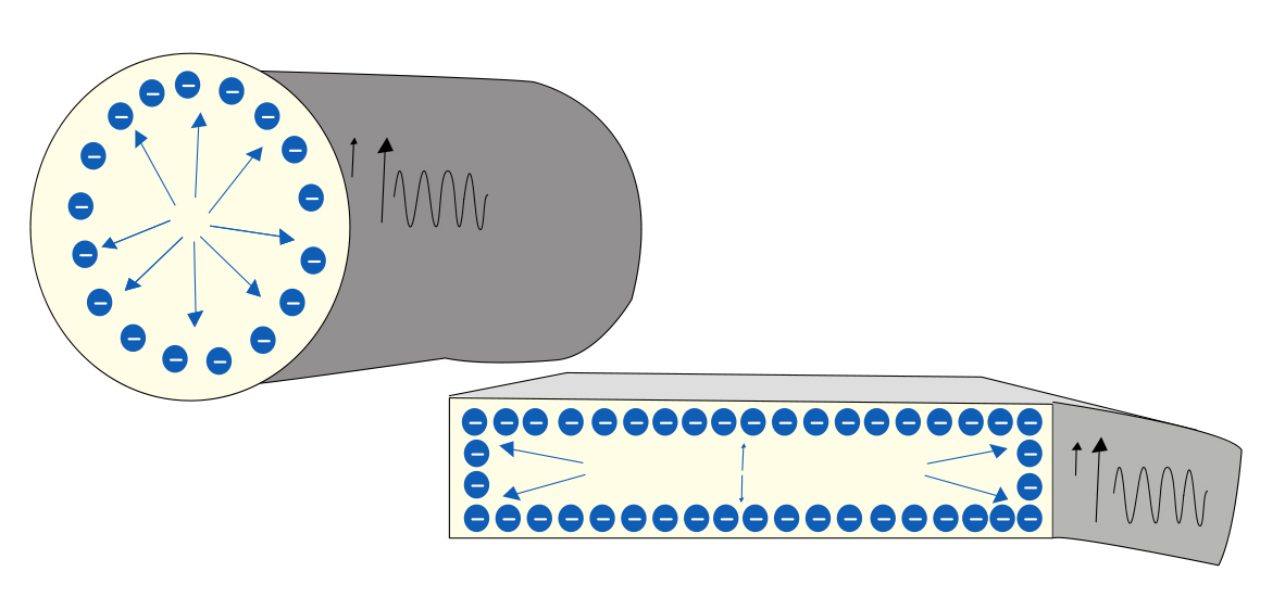
- Skin effect
A charged free electron moves across the conductor and evenly scatters other electrons. However, the wire itself is surrounded by a magnetic field that depends on the direction of the current flow. When a conductor carries a high-speed signal, its magnetic field causes self-induction, increasing separation pressure on its outer surface. Current flows primarily between the outer surface (skin) and a level called the skin depth. The skin depth varies with the frequency of the alternating current. With increasing frequency, alternating current flows to the surface, and skin depth decreases. Due to this, the effective cross-sectional area reduces, and effective resistance increases.
The ribbon offers a large surface area in proportion to the cross-sectional area. Hence, it results in greater power efficiency.
- Ribbons allow for bond stacking, which is beneficial for high-frequency applications.
- It offers better mechanical loop stability.
A wedge bonder has the workability to run either round wire or ribbon wire of aluminum or gold material. Ribbon bonding’s technological advances lead to higher yield and product efficiency.
For a successful and reliable bonding, characteristics such as the shape and size of the bond, the form of a wire loop, the bond position, and the material selection are critical. Nowadays, gold bonding is widely preferred in the semiconductor industry.
To understand the method of constructing a cost-efficient board, download our design guide.

Design for Manufacturing Handbook
11 Chapters - 96 Pages - 90 Minute ReadWhat's Inside:
- Annular rings: avoid drill breakouts
- Vias: optimize your design
- Trace width and space: follow the best practices
- Solder mask and silkscreen: get the must-knows
Download Now