


Contents

On-demand webinar
How Good is My Shield? An Introduction to Transfer Impedance and Shielding Effectiveness
by Karen Burnham
Controlled impedance PCBs often include a measurement “coupon”, which typically includes sample traces, 6 inches long and constructed as part of the printed circuit board panel. They are measured to assure the PCB stack-up and the accuracy of the PCB transmission lines. These coupons, as well as the actual PCB signal traces, interconnects and cables are typically measured using a Time Domain Reflectometer (TDR). A TDR is generally a large, expensive instrument that includes a high-speed edge pulse and a sampling oscilloscope.
Most modern circuit designs depend on accurate logic signals at the logic receiver. This assurance is based on the careful design of printed circuit board (PCB) transmission lines, interconnects, and cables. For that matter, it is advisable to verify the instrument cables and interconnects at regular intervals. Cable crimps frequently degrade, particularly in low-cost cables, and can significantly impact the quality of the measurement.
PerfectPulse®
PerfectPulse®, from Picotest, is a low-cost, pocket-sized pulse generator (J2151A). The signal generator, combined with an included resistive port splitter, and a real time oscilloscope can be used as a precise TDR/TDT measurement systems. It can measure PCB test coupon impedance, cables and bad crimps, trace length, dielectric constant (Dk), and velocity factor (Vf). This application note shows how to measure PCB, cable, and interconnect impedance, dielectric constant, velocity factor and cable length with J2151A.
Theory of the TDR Measurement
Signals travel in air at the speed of light, approximately 3 ∙ 10^8 m/sec [1]. The signal velocity is slowed when travelling over a dielectric material. The amount it is slowed down is the velocity factor (Vf) of the signal transmission, sometimes referred to as the velocity of propagation.
Coaxial cable specifications often include the velocity factor, which is typically between 60% and 90% (1). A cable with a velocity factor of 70% means that the signal travels at 0.7 times the speed of light or 2.1 ∙ 10^8 m/sec.
The velocity factor is directly related to the permittivity of the transmission line. The ratio of the permittivity of a cable, or printed circuit board to the permittivity of free space is the dielectric constant of the transmission line or PCB. Dielectric constant is sometimes expressed as εr and sometimes as Dk. Typical dielectric constant values range from a low of about 2 to as high as about 24.
The relationship between the velocity factor and the dielectric constant is:
![]()
Since we know that the signal propagates through the cable or PCB at a speed of light reduced by the velocity factor it is possible to relate time and distance.
![]()
Solving the signal propagation in units of inches and picoseconds
![]()
And therefore, a round trip through the trace or cable is
![]()
And solving for Dk from a known length
![]()
In a single-ended TDR measurement, the high-speed edge travels from the beginning of the transmission line to the end of the transmission line and then reflects to the instrument where it is measured. The signal makes a round trip through the transmission line and the instrument uses the incident and returned signals to measure the propagation time and the reflection coefficient, Γ, which is used to compute the transmission line impedance.
![]()
where ZTL is the transmission line impedance and Zo is the reference impedance, typically 50Ω.
Solving for impedance,
![]()
Putting this all together, the TDR source generates a fast-edge signal, which is split into two equal magnitude signals. One signal is used by the oscilloscope to monitor the reflection signal and the other signal is delivered to the transmission line. The reflected voltage is used to calculate the impedance while the round-trip signal time is used to calculate either the dielectric constant of the transmission line or the length of the transmission line, depending on which of the values is unknown. The dielectric constant can be determined from the signal propagation time and the length can be determined from the signal propagation time and the velocity factor, Vf.

Measurement Setup
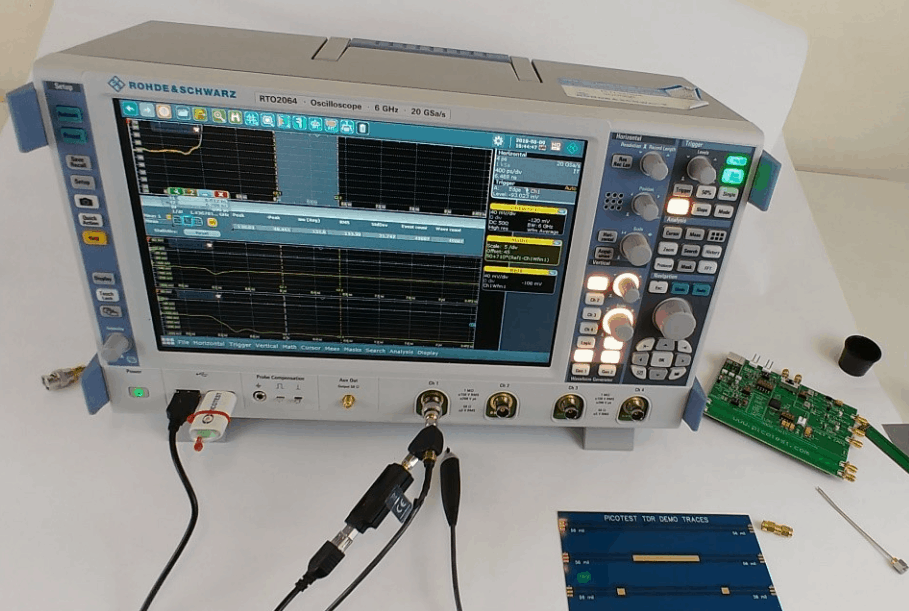
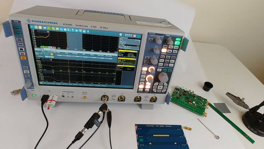
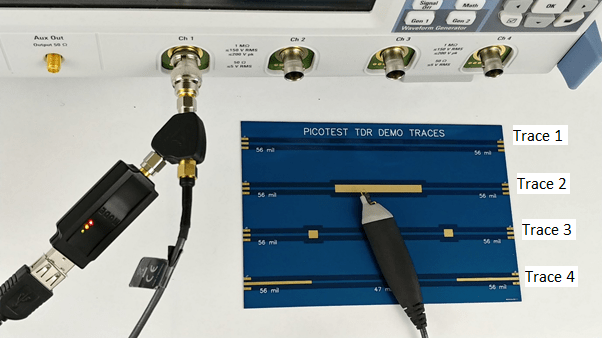
Figure 1 shows a picture of the TDR measurement setup. One TDR splitter port is connected to the oscilloscope. Since many lower bandwidth scopes use BNC connectors an RF adapter might be required. High-quality adapters, preferably calibration quality adapters are recommended. The second TDR port is connected to the measurement sample using a high-quality cable, high bandwidth 1-port probe, or connectors as applicable. Figure 2 shows the Picotest demo board used in the measurements in this application note.
The general procedure to make the TDR connections are,
1. Connect the J2151A to the port splitter and connect the port splitter to the oscilloscope as shown in Figure 1. Connect a coaxial cable or probe to the TDR port of the splitter.
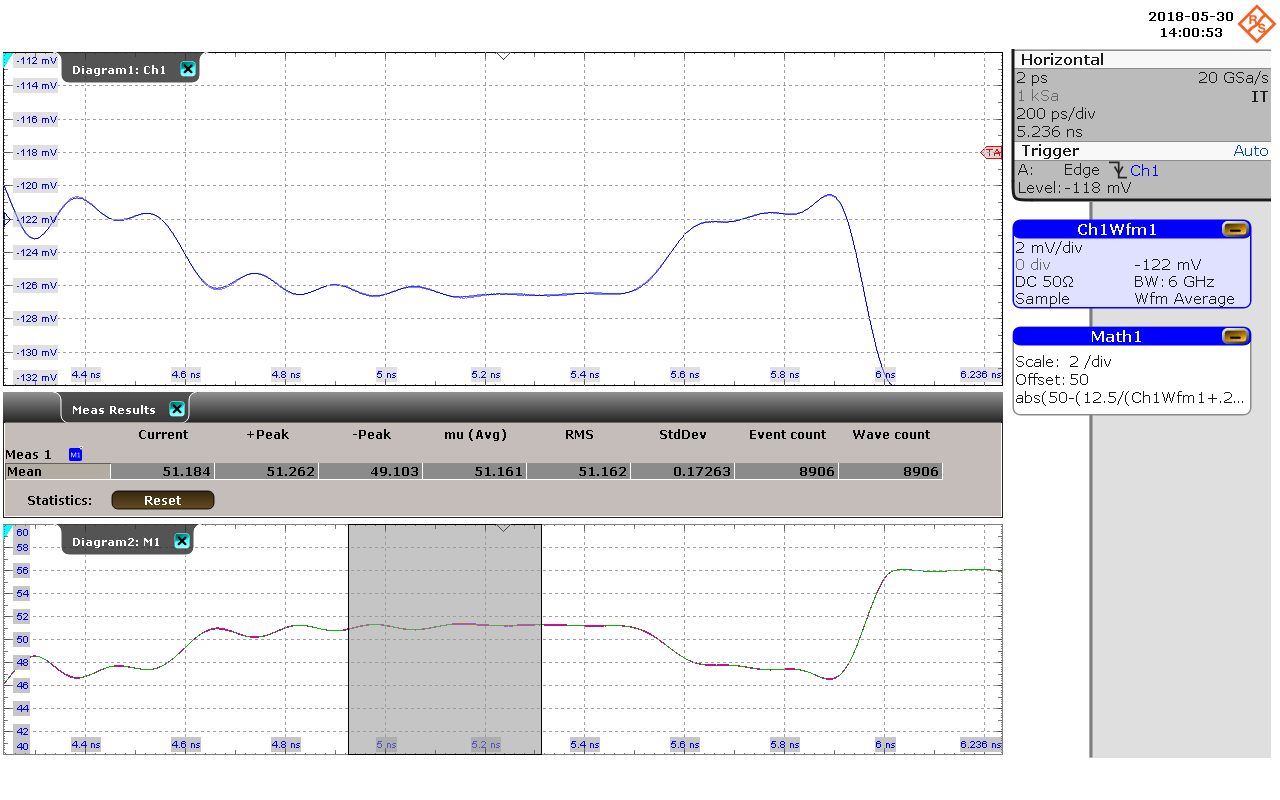
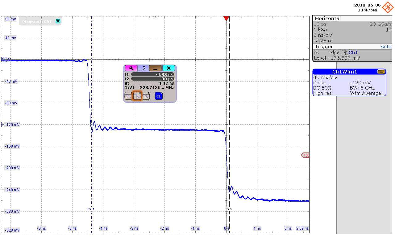
2. Set the oscilloscope trigger slope to the falling edge and set the trigger close to the left side of the screen.
3. Use a measurement function or place cursors to measure the width of the negative pulse. The functions or methods used for each measurement are discussed in the following sections.
Measuring PCB, Cable and Interconnect Impedance
The measured oscilloscope voltage can be converted into impedance by the following equation,
![]()
Where RDUT is the impedance of the device under test (DUT), RGEN is the generator output impedance (50 ohms), and VSCOPE is the voltage received in the oscilloscope (-500 mV). This can be further reduced as,
![]()
The equation can usually be applied within the oscilloscope, using a math function, to obtain the impedance. The scope values can also be exported to use with a program like Mathcad, Matlab, or Octave to plot the DUT impedance functions using this equation.
Measuring Dielectric Constant and Velocity Factor
No calibration is required for the measurement of dielectric constant. This is a time measurement and based on a known value of length, the dielectric constant, Dk, can be determined from (5). Velocity factor (Vf) can be determined from (1) for a known value of length. The measurement setup in shown in Figure 1.
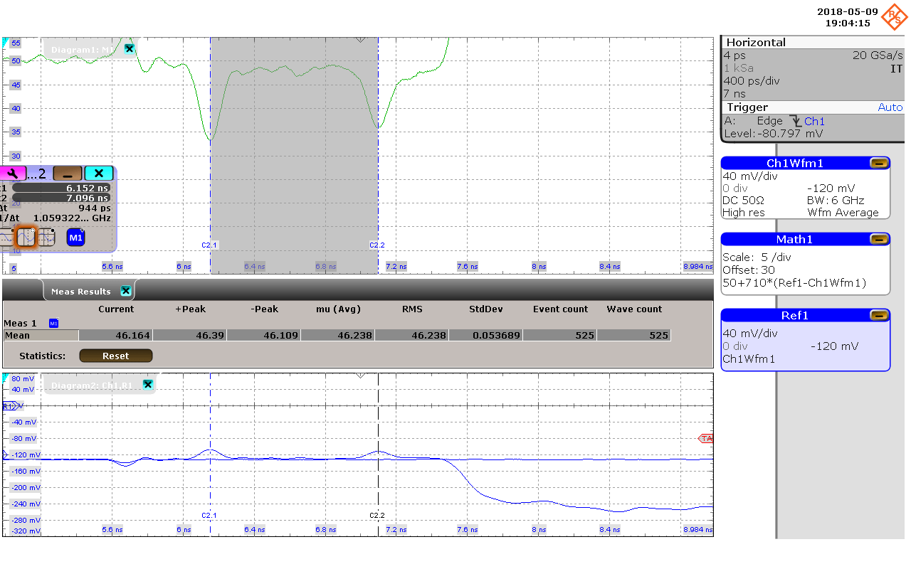
Measuring Trace or Cable Length
It is assumed that the cable velocity factor is known prior to the measurement and most cable manufacturers publish this parameter. If not, a small known piece of the cable can be cut to measure the velocity factor as shown in the previous section. After measuring the round trip time using TDR-oscilloscope combination, we can measure the length using (4) with the known value of Vf. An example is shown in Figure 5.
Tips for Measurement
- Use high quality cables and probes. If RF adapters are required, use calibration quality adapters.
- Measure the flattest portion of the impedance signal. This is typically between 50% and 75% of the trace/cable length.
- Using gated cursors to obtain the mean value in this range.
- Reducing the bandwidth degrades resolution but provides a lower noise result. A standard IPC coupon can generally be measured using a 1GHz-2GHz oscilloscope.
The Picotest J2151A is a good choice for low cost TDR/TDT using an existing oscilloscope. It can be used to measure PCB test coupons impedance, to test cables and bad crimps, trace length, Dk, and velocity factor. This application note shows how to use J2151A to measure PCB, cable and interconnect impedance, dielectric constants (Dk), velocity factor (Vf) and length. For additional information and products please visit https://www.picotest.com/measurements/MeasuringPCB.html.
[1] The actual speed of light is 2.99792458 ∙ 10^8 m/sec, so 3 ∙ 10^8 m/sec is a reasonable approximation.
For more design information, check with our DESIGN SERVICE team.

High-Speed PCB Design Guide
8 Chapters - 115 Pages - 150 Minute ReadWhat's Inside:
- Explanations of signal integrity issues
- Understanding transmission lines and controlled impedance
- Selection process of high-speed PCB materials
- High-speed layout guidelines
Download Now


