Contents

On-demand webinar
How Good is My Shield? An Introduction to Transfer Impedance and Shielding Effectiveness
by Karen Burnham
This NASA case study was originally published in Tech Briefs. It was written by Joshua Forgione, Electronics Engineer, NASA Ames Research Center. Carl Sorenson, Sensor Engineer, NASA Dryden Flight Research Center also contributed to this article.
Network Interface Links Sensor-Web Instruments
NASA Airborne Science operates a fleet of aircraft in conjunction with orbiting satellites for Earth observations. In 2004, NASA started planning missions to employ constellations of instruments flying on those platforms. They would mutually interact and communicate as a network with stations on the ground. These sensor webs would simultaneously collect data from multiple perspectives to better describe hurricanes, polar ice conditions, and other geophysical dynamics. Data from various spectra and locations could be correlated in real time to form detailed composites of events in progress.
NASA aircraft had for decades collected atmospheric and terrestrial information for a wide range of Earth science research conducted by universities, companies, and government agencies such as the National Oceanic and Atmospheric Administration (NOAA). Pilots switched on the instruments, the data were acquired, and the recordings were unloaded and analyzed after the aircraft landed. To standardize instrument connections to the ER-2 high-altitude aircraft , NASA created the Mark 1 Experimenter Interface Panel (EIP) in the 1990’s. It provided power to the payloads and a link to a pilot-operated switch panel. That EIP was a largely a harness pass-through with a small printed circuit board. This PCB carried low-level relays for the cockpit switch panel. It simplified the engineering required to deploy instruments to the ER-2, and was later installed on the WB-57 aircraft.
However, the system provided no visibility into the instruments’ power consumption or other onboard conditions. Unless a payload provided one , there was no capability for high-bandwidth data transmission from the NASA Airborne Science aircraft. Researchers had no insight about data or instrument operation during flights, except by audio communication with pilots who often had two lamps per instrument no monitor. A science team could pay tens of thousands of dollars for fuel, only to discover after hours of post-flight data processing, that their instruments malfunctioned or an unforeseen target of interest was missed.
Developing Sensor Net
The development of a new “Sensor New” payload system (Figure 1) began in 2008, when the Global Hawk Unmanned Aerial Vehicle (UAV) was added to the Airborne Science fleet. This in turn motivated development of a fleet-wide standard electrical interface for research instruments. The Airborne Payload C3 System (APCS) in the Global Hawk incorporated prototypes of a new (Mark II) EIP, a NASA Airborne Science Data Acquisition and Transmission Unit (NASDAT), and an Ethernet network by which the NASDAT – the network server – would distribute a precise timing reference, navigation data, and avionics data among experiment instruments.
Each instrument would report its status through an EIP via the network to the NASDAT. And each EIP would update the NASDAT via the network about the DC power consumption of the instruments, cockpit switch states, and related ship-side housekeeping details, which the NASDAT would store and rebroadcast to the instruments.
The NASDAT would provide limited communication with ground stations over Indium satellite telephone modems. The Link Module, a commercial off-the-shelf unit, would provide 5000 Gbytes of mass storage, serve as a gateway to high-bandwidth communications to enable researchers on the ground to view data in real time, and would process some data onboard as they were being collected.
The first flights for the APCS were on the GLOPAC mission aboard the Global Hawk in 2010, which included a flight of record-breaking duration for that UAV.
Sensor-Web Instruments
The payload included 11 networked instruments, which scientists used to collect data, and stratospheric air masses that had moved from the North Pole. Observations from the Global Hawk were also used to validate atmospheric data from the Aura and CALIPSO environmental monitoring satellites.
Spanning the Fleet
The Mark II EIP’s developed for the Global Hawk were a success, but were optimized for that aircraft and did not span the requirements of the entire fleet, which includes such diverse aircraft as the DC-8, P-3B, B200, the ER-2, the WB-57, and others. In particular, because the Mark II EIP was dedicated to a remotely controlled aircraft, it did not provide an interface for manned cockpit switches. More ever, it did not support such legacy data-communication protocols as ARINC-429, RS-232, RS-422, or Synchro.
Through those protocols and their hardware interfaces may seem outdated, the expense and engineering effort required to convert or redesign the many dozens of existing instruments that incorporate them would be major. Consequently, in 2010, the NASA Airborne Sensor Facility began development of the Mark III EIP, a fleet-wide design that accommodates existing instruments that have legacy interfaces, as well as new payloads with 10BASE-T, 100BASE-TX, or 1000BASE-T data interfaces.
The Mark III EIP ship-side connections are backward-compatible, mechanically and electrically, with the Mark I. The Mark III EIP is a drop-in replacement for all the aircraft in the fleet, including the ER-2 and WB-57, which have the most stringent power and volumetric requirements.
ER-2 and WB-57 pilots control instruments exclusively from the cockpit, and the new EIP carries forward an interface to the cockpit switch panel for those and other aircraft. Unmanned installations substitute an onboard Master Payload Control System (MPCS) in place of the pilot, which is software controlled through a communications link. Whether aircraft are manned or unmanned, for safety, the controls or avionics and the switches to power instruments are hardwired and isolated from those for instrument communications, data collection, and instrument adjustment in flight.
Ethernet network
The new EIP supports all the legacy data protocols of existing instruments, but the primary data interface for new payloads is an aircraft’s payload Ethernet network. Each EIP incorporates and Ethernet switch with four 1000BASE-T and eight 10/100BASE-T ports available to instruments. In a typical installation, two 1000BASE-T ports are consumed by the ring network backbone, leaving ten of the ports available for payloads.
Each Mark III EIP contains 12 commercial solid-state power controllers for distribution of 28-V DC power, the Ethernet switch card, and four custom printed circuit boards that tie everything together. Sierra Circuits fabricated several of the boards in the Mark III EIP. NASA airborne instruments typically operate from 28-VDC or three-phase, 115-V, 400-Hz AC. The EIP itself does not switch, protect, or measure AC, but merely distributes the current from shipside to four outputs for instruments. That duty is consolidated on a single custom board, instead of a conventional terminal-block implementation, which would have consumed too much space. The total AC power available is 17.25 kVA, with a wide safety margin for transients.
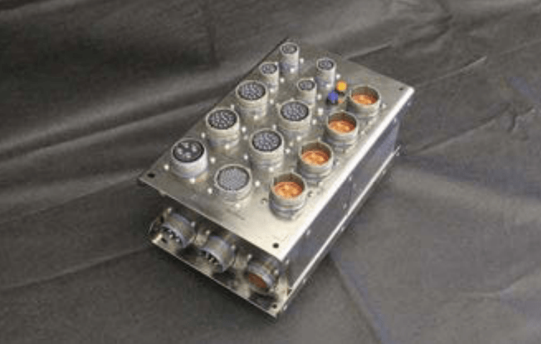
fleet of NASA aircraft, supports the data protocols of legacy instruments, and provides ten high-speed
Ethernet ports (via the four large connectors along the lower edge).
There are five connectors to power instruments. Four of them each include two circuits of three-phase AC (15 A per phase) and two circuits of 28-V DC (15 A apiece). Those connectors duplicate the pin assignments of the Mark II power interface designed for the Global Hawk, and provide the same supply of AC and DC as the Mark I EIP. The fifth socket, whose pinout duplicates that of a power connector on the Mark I, supports legacy instruments, providing up to 40A of 28-VDC on each of two circuits.
Simultaneous data acquisition
Each Mark III EIP supports up to four scientific instruments for simultaneous data acquisition. There are multiple bays in each aircraft to house one or more EIPs and their associated instruments. But thanks to the Mark III EIP, they can now be flown universally on the many different aircraft of the fleet, which increases mission flexibility and the number of research flight opportunities.
Moreover, the ability to network instruments within and among aircraft in flight, in coordination with satellite-base instruments, opens opportunities for far more detailed definition of the atmosphere. Using the Mark III EIP, NASA Airborne scientists can acquire more data simultaneously than ever before to better comprehend our environment as a whole.
Read our HDI case study.