Speak to an Account Manager
![]() +1 (800) 763-7503
+1 (800) 763-7503
Tools for Designers:
Trace Width, Current Capacity and Temperature Rise Calculator
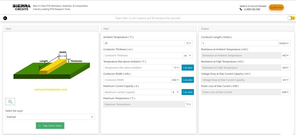
Input Your Specs to Get StartedSierra Circuits’ Trace Width, Current Capacity and Temperature Rise Calculator is an advanced PCB tool that works based on the latest IPC-2152 standard. It’s a three-in-one calculator. If you know the values of any of the two parameters (conductor width, max temperature, max current capacity) it determines the third. This trace width calculator also computes resistance at ambient and high temperatures, voltage drop, and power loss at maximum current for internal and external traces.
The current carrying capacity of a conductor depends on its width and thickness. If the width of the signal line is not sufficient, the trace may burn out and impact the functionality of your board. Calculating the ideal trace width is crucial to achieving design success. In addition to the physical characteristics of the line, you should also keep an eye on its temperature.
The IPC 2152 talks about how the temperature rises in various signal lines (internal and external) due to the current flow. This document depicts the results in graphical format. We have studied those graphs to derive curve-fitting formulae and incorporated them into this tool.
Features of the calculator
- Calculates conductor width, maximum current capacity, temperature rise above ambient, maximum temperature, resistance at ambient and high temperatures, voltage drop, and power loss at maximum current for internal and external traces.
- Results are based on the formulae derived from the graphs in the IPC 2152 standard.
- Supports multiple units of conductor thickness and width, current, resistance, power, and temperature.
How to use the Trace Width, Current Capacity and Temp Rise Calculator
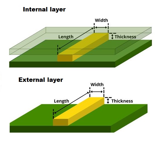
To calculate the conductor width, you need to first select the layer (external or internal) and enter the values of the following parameters:
- Ambient temperature
- Conductor thickness
- Temperature rise above ambient
- Maximum current capacity
- Conductor length
The default value of ambient temperature is 25°C. However, you can also enter a different value as per your requirement. The standard value of conductor length is 1 inch. You can modify this dimension as desired.
Please note that you can change the units of these input parameters by using the respective drop-downs.
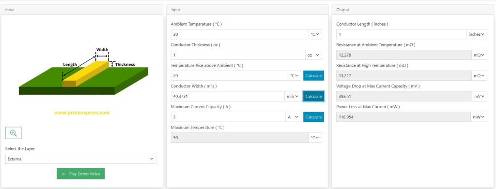
After entering the values, click calculate (adjacent to the conductor width field). The tool now displays the optimum conductor width. In addition to this, you can also view the values of resistance at ambient and high temperatures, voltage drop, and power loss at maximum current.
For instance, let’s calculate the conductor width for an external layer with the following characteristics:
- Ambient temperature = 30°C
- Conductor thickness = 1 oz
- Temperature rise above ambient = 20°C
- Maximum current capacity = 3 A
- Conductor length = 1 inch
You can see that along with the conductor width, 40.373 mil, the tool displays the values of the following parameters:
- Maximum temperature = 50°C
- Resistance at ambient temperature = 12.27 mΩ
- Resistance at high temperature = 13.21 mΩ
- Voltage drop at maximum current capacity = 39.651 mV
- Power loss at maximum current = 118.954 mV
Similarly, if you’d like to calculate the maximum current capacity of a trace, you need to enter the following values and hit calculate (beside maximum current capacity).
- Ambient temperature
- Conductor thickness
- Temperature rise above ambient
- Conductor width
- Conductor length
The same steps can be followed to compute temperature rise above ambient. The only difference here is that you need to enter all the previously mentioned parameters (except temp rise) and click calculate (beside temperature rise above ambient).
By using the Trace Width, Current Capacity and Temperature Rise Calculator you can compute the ideal line width, and temperature rise for a given current in a go. This not only saves your design time but also helps you choose the right copper features to build a reliable PCB. For more such tools, visit our designer’s tools page.
Watch the demo of our Trace Width Calculator

Sierra Circuits has developed easy-to-use tools for PCB Designers and Electrical Engineers at every stage of circuit board development.


Fabrication, Procurement, & Assembly. PCBs fully assembled in as fast as 5 days.
- Bundled together in an entirely-online process
- Reviewed and tested by Engineers
- DFA & DFM Checks on every order
- Shipped from Silicon Valley in as fast as 5 days

Fabrication. Procurement & Assembly optional. Flexible and transparent for advanced creators.
- Rigid PCBs, built to IPC-6012 Class 2 Specs
- 2 mil (0.002″) trace / space
- DFM Checks on every order
- 24-hour turn-times available

Complex technology, with a dedicated CAM Engineer. Stack-up assistance included.
- Complex PCB requirements
- Mil-Spec & Class 3 with HDI Features
- Blind & Buried Vias
- Flex & Rigid-Flex boards