PCB Interfaces and Communication Protocols Handbook
Sierra Circuits' PCB Interfaces and Communication Protocols Handbook helps you choose the right connector based on data rate, power requirements, and design needs.


The PCB Interfaces and Communication Protocols Handbook provides practical information on the electrical and logical connections that enable data exchange between components, boards, and external devices.
The protocol type determines how data moves between devices. Each has its own topology, signaling method, communication mode, data rate, operating distance, advantages, and limitations.
Understanding these differences helps you select the right protocol based on your design’s electrical and functional requirements.
Here’s a quick breakdown of what you’ll learn in this guide:
- How communication topology and interface selection affect data transfer between devices
- Key characteristics and applications of serial protocols such as UART, SPI, I2C, and I2S
- How wired technologies such as RS-232, RS-485, USB, Ethernet, CAN, and HDMI support different communication needs
- How high-speed communication protocols such as LVDS, PCIe, MIPI, DDR, SDIO, and eMMC enable data transfer in embedded systems
- How wireless technologies such as Wi-Fi, Bluetooth, ZigBee, LoRa, NFC, 5G, and Z-Wave support short-range and long-range connectivity
How to select the right circuit board interface?
Choosing an appropriate protocol involves balancing several design requirements rather than simply prioritizing data rate.
Consider the following factors:
- Data transfer speed: The protocol must support the amount of data that needs to be transmitted. Low-speed sensor communication can use interfaces such as I2C, while high-bandwidth applications may require PCIe, Ethernet, USB, or other high-speed technologies.
- Communication distance: Some models are intended for data exchange between devices located only a few centimeters apart on a PCB. Others support much longer connections through cables or network infrastructure.
- Number of devices: Some connectors are designed primarily for point-to-point communication, while others support multiple devices sharing a bus or network.
- Power consumption: Power-sensitive applications may prioritize models that support low-power operation. This is particularly important in battery-powered and wireless products.
- System complexity: Simple interfaces can reduce the number of signal lines and simplify implementation. More sophisticated ones may provide higher bandwidth or greater functionality but require more complex routing and system design.
- Environmental conditions: Industrial and automotive systems can operate in electrically noisy environments. Differential signaling and robust communication mechanisms can make certain protocols more suitable for these applications.
What are the different types of PCB interfaces?
PCB communication protocols can broadly be divided into wired and wireless.
Wired ones use physical or optical connections to transfer data. The connection may consist of traces, cables, twisted pairs, or fiber-optic links.
Examples: UART, SPI, I2C, USB, Ethernet, CAN, PCIe, and HDMI.
Wireless protocols transmit information without a direct electrical connection between the communicating devices. Instead, they use radio-frequency signals to establish a connection.
Examples: Wi-Fi, Bluetooth, ZigBee, LoRa, NFC, 5G, and Z-Wave.
The choice depends on the application’s communication requirements. For example, an MCU connected to a nearby sensor can use a simple interface such as I2C or SPI. Networking applications may require Ethernet or Wi-Fi, while industrial systems with longer communication links often use RS-485 or CAN for their differential signaling and noise immunity.
1. Universal asynchronous receiver/transmitter (UART)
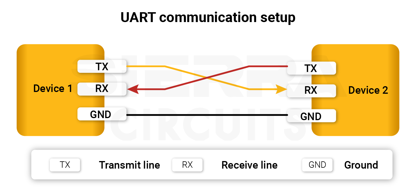
UART is a simple asynchronous serial communication interface that transmits data one bit at a time. Unlike synchronous ones such as SPI and I2C, UART does not use a shared clock signal. Instead, the communicating devices agree on a baud rate so that the receiver can correctly interpret the transmitted data.
This model typically uses separate transmit and receive lines (TX and RX), enabling full-duplex communication between two devices. It is commonly used for microcontroller-to-peripheral communication and connections to modules such as GPS and Bluetooth devices. UART is attractive because of its simple implementation and low resource requirements. Its limitations include relatively short communication distances and basic error detection.
2. Serial peripheral interface (SPI)
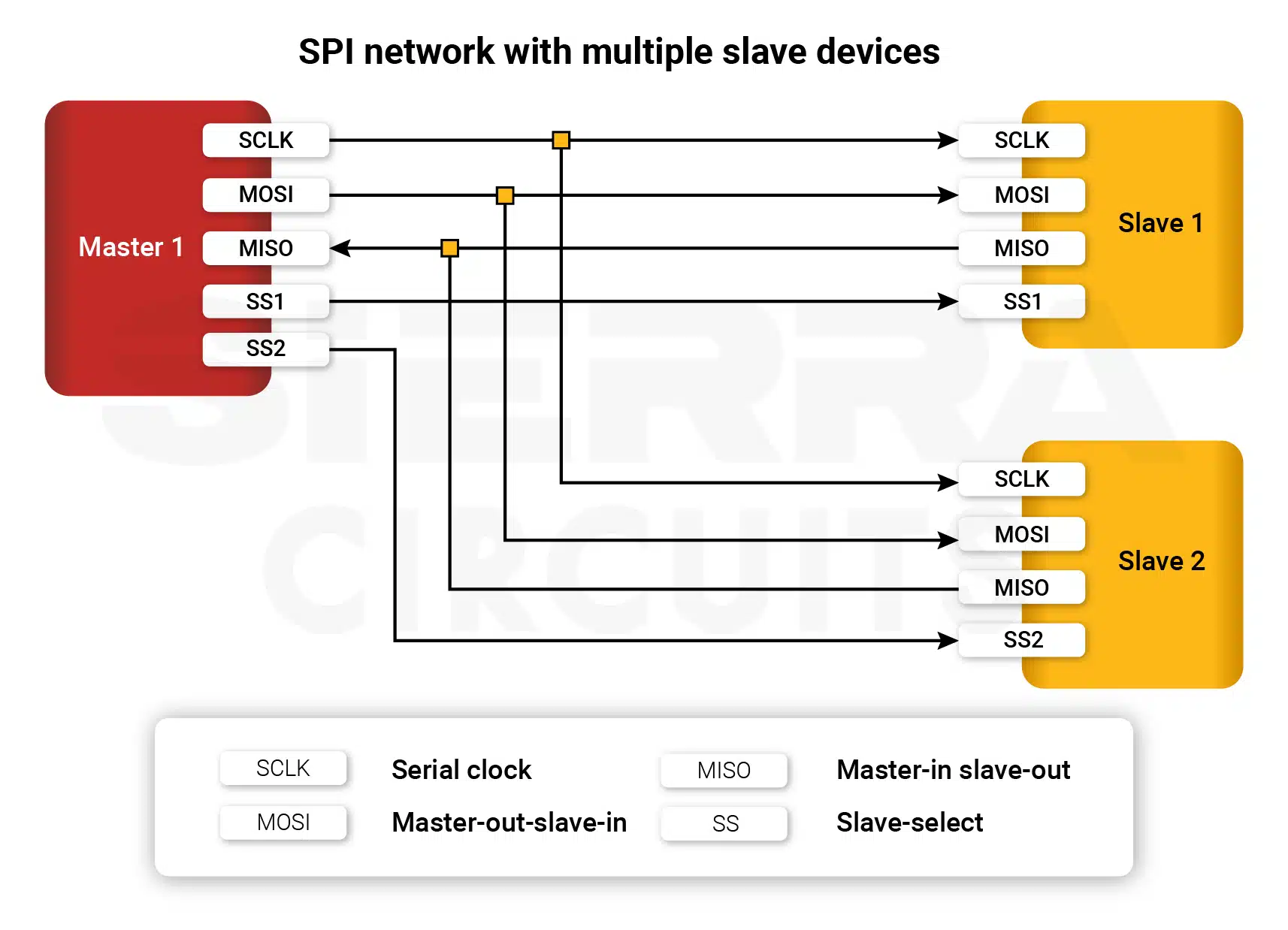
SPI is a synchronous serial communication interface designed for high-speed communication between a controller and peripheral devices. It commonly uses four signals: MOSI, MISO, SCLK, and SS. The clock synchronizes data transmission, while separate transmit and receive lines allow full-duplex communication.
It is used to connect microcontrollers with sensors, ADCs, DACs, memory devices, and displays. Its major advantage is speed and straightforward hardware implementation. However, connecting multiple devices can require additional chip-select lines, and SPI is generally intended for short-distance, board-level communication.
3. Inter-integrated circuit (I2C)
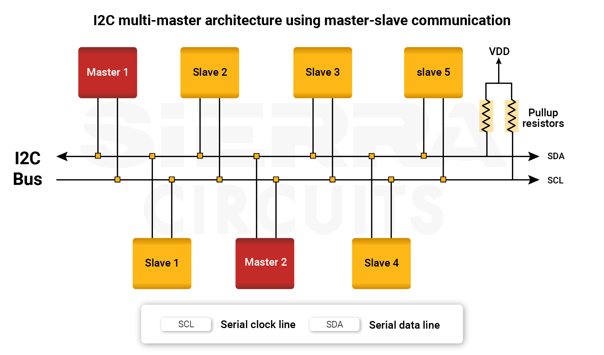
I2C is a synchronous serial communication protocol that uses two primary signal lines: SDA for data and SCL for the clock.
Multiple devices can share the same bus, with each device identified through an address. This makes I2C particularly useful when several low-speed peripherals need to communicate with a controller without requiring a separate communication interface for every device.
I2C is commonly used for sensors, EEPROMs, real-time clock devices, ADCs, DACs, and other peripherals. Its two-wire structure reduces routing requirements, but its speed and communication distance are lower than those of many high-speed interfaces.
4. Universal serial bus(USB)
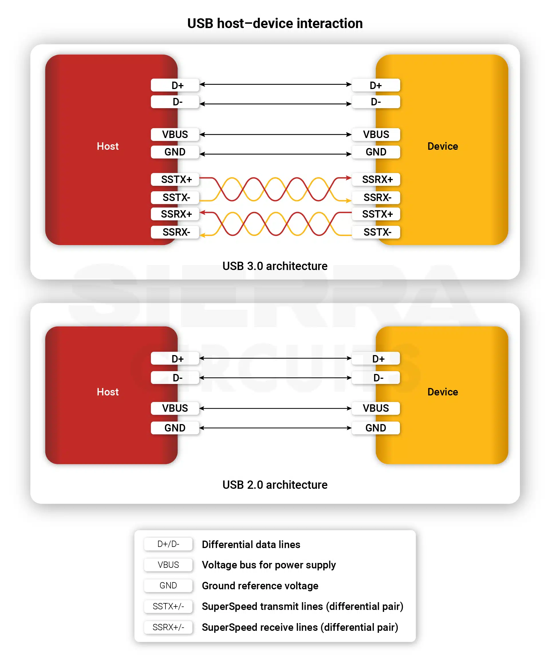
USB is a standardized wired interface used to connect computers, embedded systems, and peripheral devices. It supports both data transfer and power delivery through the same physical connection. Different USB generations provide different data rates, with newer versions supporting substantially higher bandwidth.
It is widely used because it supports plug-and-play operation and provides a standardized method for connecting peripherals such as storage devices, smartphones, and other electronic equipment. USB 2.0 uses differential data lines along with power and ground, while higher-speed versions add additional differential pairs to support increased bandwidth.
5. Ethernet
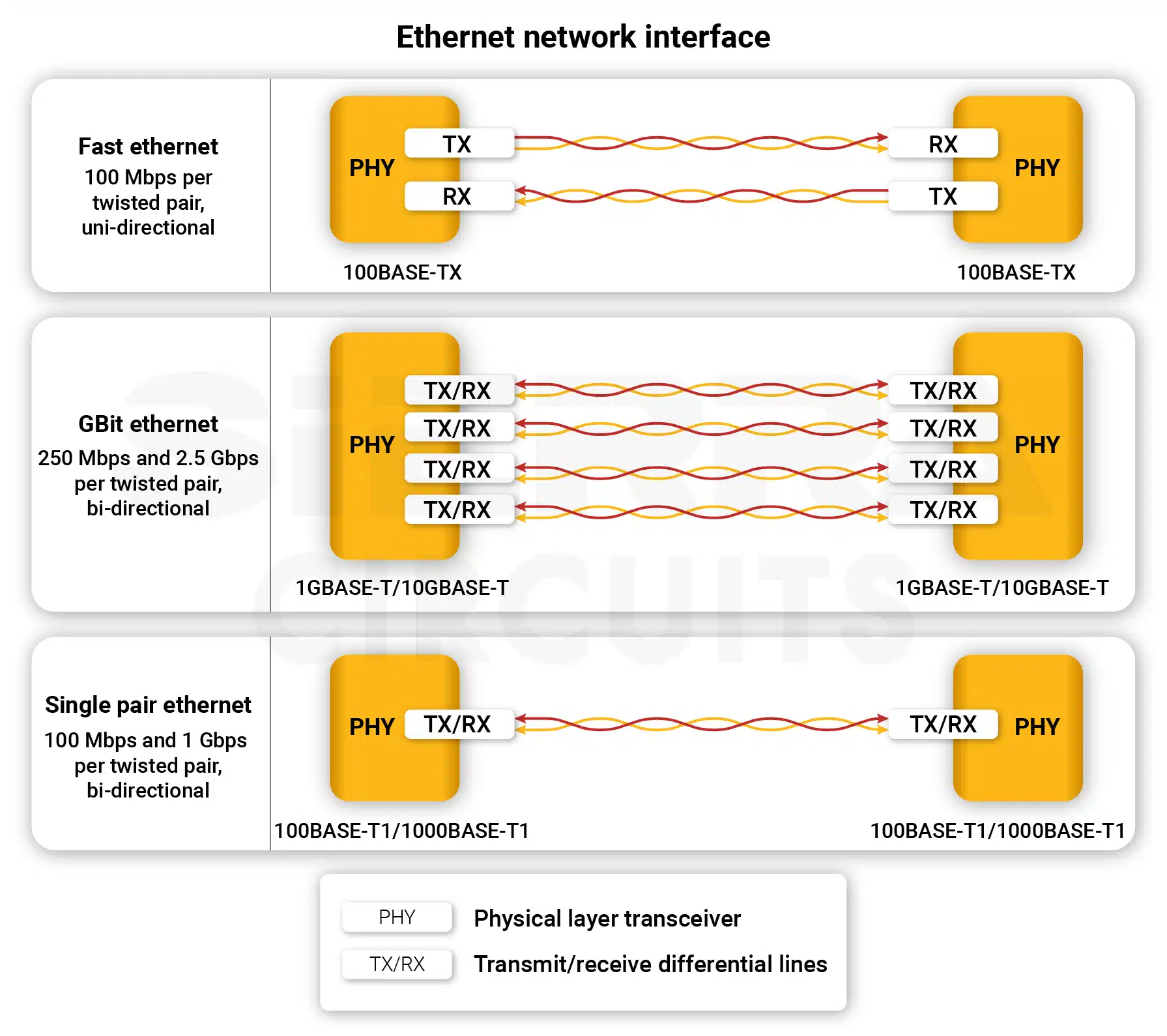
Ethernet is a wired networking technology used to connect devices within local networks and larger network infrastructures. It communicates using frames and can operate over copper twisted-pair cables or fiber-optic connections.
Depending on the implementation, Ethernet supports data rates ranging from relatively low-speed networking to hundreds of gigabits per second. Its applications include local-area networks, industrial automation, servers, IoT equipment, and network-connected embedded systems.
Ethernet provides standardized, reliable communication, but its implementation depends on the appropriate network infrastructure, cabling, and networking equipment.
6. Low-voltage differential signaling (LVDS)
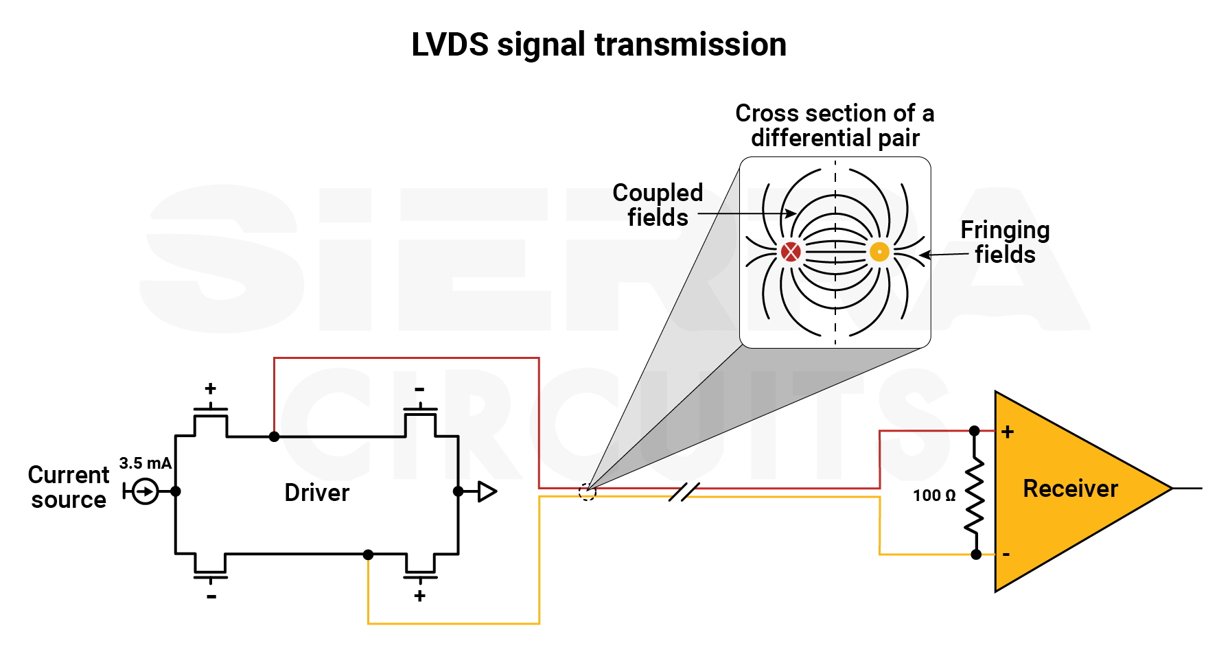
LVDS uses differential pairs to transmit high-speed data with relatively low power and low noise.
Instead of measuring a signal relative to ground, the receiver determines the voltage difference between two conductors. This differential approach improves immunity to common-mode noise and reduces electromagnetic interference.
LVDS is commonly used for displays, high-speed cameras, medical equipment, memory interfaces, and other applications requiring fast data transmission.
Since LVDS relies on controlled differential signaling, PCB layout must account for differential impedance, pair matching, routing symmetry, and signal integrity. Sierra Circuits
7. Peripheral component interconnect express (PCIe)
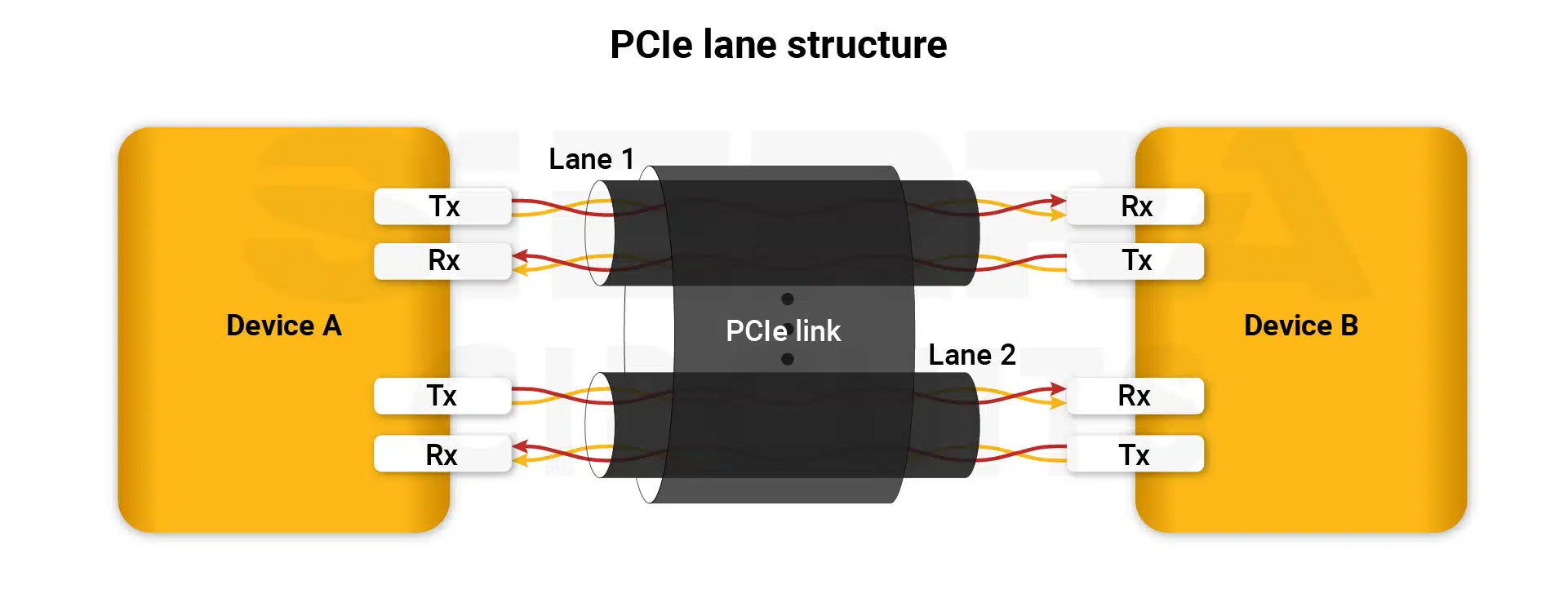
PCIe is a high-speed serial interface used for communication between processors and high-performance peripherals such as storage devices and expansion hardware.
Unlike lower-speed interfaces intended for simple peripheral communication, PCIe is designed for high-bandwidth data transfer. Its implementation requires careful attention to signal integrity because high-speed differential lanes are sensitive to loss, impedance discontinuities, reflections, and other transmission-line effects.
Other high-speed interfaces serve similarly specialized applications. HDMI is used to transmit high-speed digital audio and video. MIPI provides high-speed, low-power interfaces for cameras and displays in mobile and embedded systems.
DDR provides high-bandwidth communication between memory controllers and DRAM. SDIO provides a synchronous interface for SD-based peripherals, while eMMC provides embedded storage communication between a controller and flash memory.
8. DDR
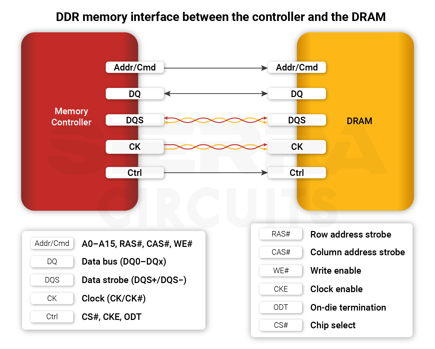
DDR is a synchronous parallel memory interface used to connect memory controllers with DRAM.
It transfers data on both edges of the clock, increasing the amount of data transmitted during each clock cycle. As DDR generations increase in speed, routing and timing requirements become increasingly demanding. The interface includes data, data-strobe, address, command, control, and clock signals. Because these signals operate at high speeds and require tight timing relationships, PCB routing must maintain signal integrity and timing consistency.
eMMC combines flash memory with a controller in a single embedded storage device. It is commonly used in smartphones, tablets, embedded systems, IoT products, and automotive electronics. Its compact implementation makes it suitable for applications where integrated, board-level storage is required.
9. Bluetooth
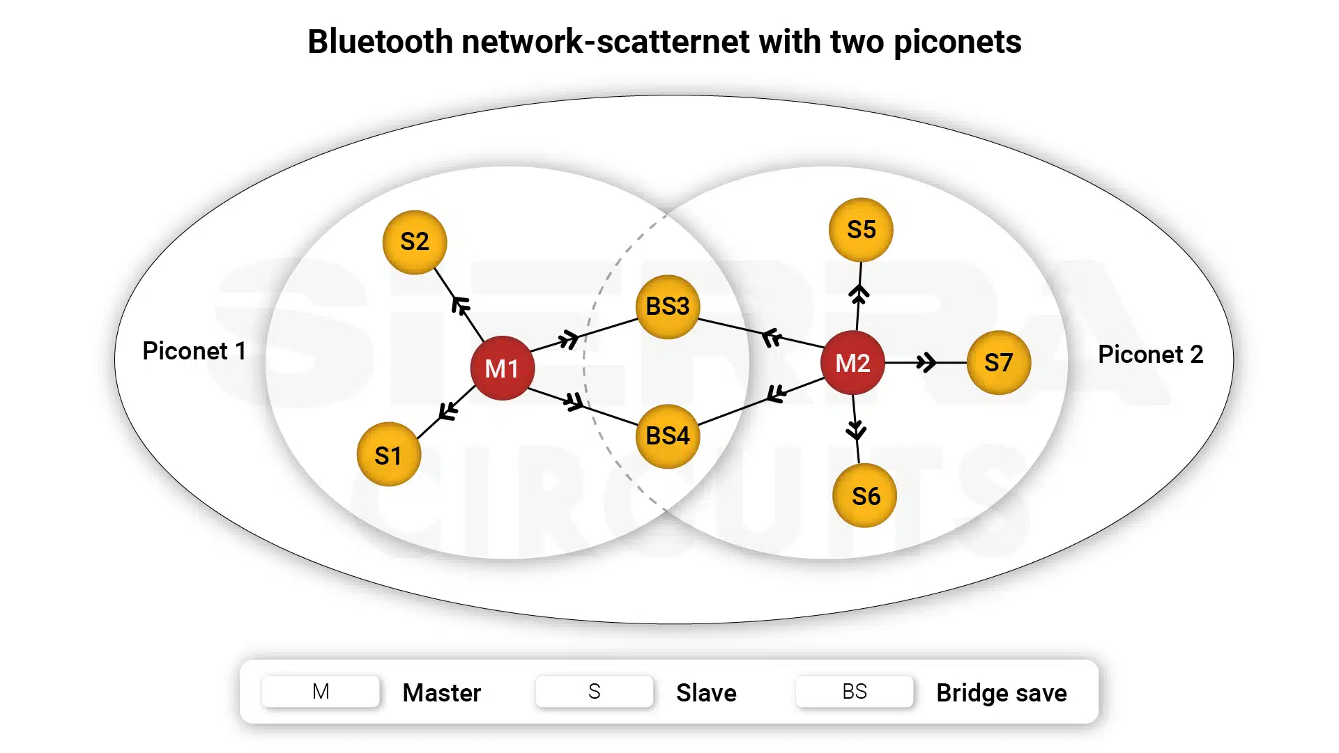
Bluetooth provides short-range wireless communication using the 2.4 GHz ISM band. It is widely used for wireless audio, IoT products, peripherals, and other applications where devices need to exchange information over relatively short distances. Bluetooth emphasizes convenient connectivity and relatively low power consumption.
Bluetooth Low Energy variants are particularly useful in applications where battery life is important. Its limited range and potential interference from other devices operating in the same frequency range must be considered during system design. Sierra Circuits
10. ZigBee
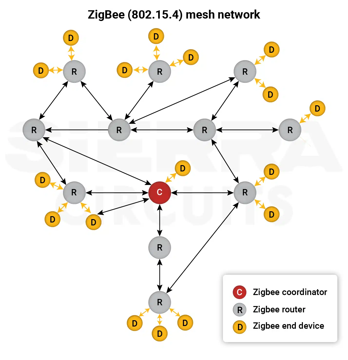
ZigBee is a low-power, low-data-rate wireless communication technology designed for applications such as home automation, industrial control, and sensing. Its mesh topology allows devices to relay messages between nodes. A coordinator manages the network, routers forward messages, and end devices communicate through their parent nodes. This architecture can extend communication coverage and provide multiple paths through a network. ZigBee is useful when low power consumption and mesh networking are more important than high data rates.
For more, download the full design guide.
How does LoRa support long-range, low-power communication?
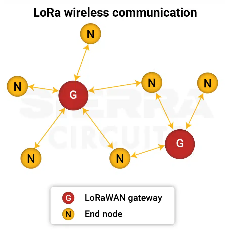
LoRa is designed for low-power, long-range wireless communication. It is suited to applications where devices need to transmit relatively small amounts of data over significant distances while conserving power.
This makes LoRa useful for IoT applications and distributed sensing systems. The trade-off is lower data rates compared with high-speed wireless technologies such as Wi-Fi. LoRa therefore fits applications where range and power efficiency are more important than high bandwidth.
How does 5G support connected devices?
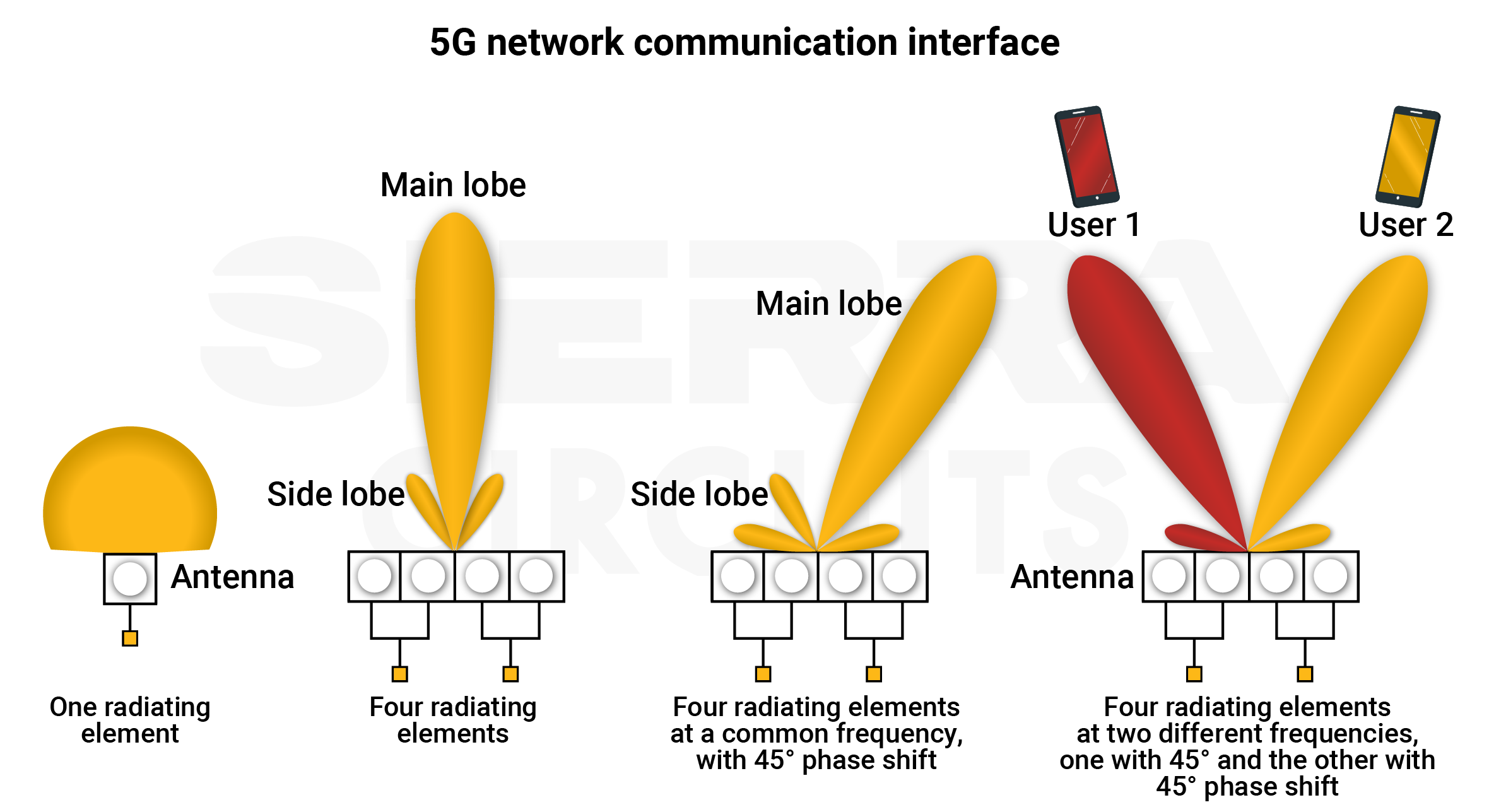
5G is a fifth-generation cellular communication technology designed to provide high data rates, low latency, and large-scale device connectivity. It operates across sub-6 GHz and millimeter-wave frequency ranges. The operating frequency affects factors such as range and propagation behavior. Applications include smartphones, IoT systems, smart-city infrastructure, and connected vehicles.
High-frequency 5G designs require careful RF implementation because signal loss and other high-frequency effects become increasingly important as operating frequencies increase. Sierra Circuits
How do PCB interfaces affect signal integrity?
They influence the physical requirements of the communication path. Low-speed protocols such as UART and I2C generally have less demanding routing requirements than high-speed models such as PCIe, DDR, MIPI, LVDS, and high-speed USB.
As data rates increase, circuit board designers need to pay greater attention to transmission-line behavior, impedance, signal loss, crosstalk, and routing geometry. Differential interfaces require carefully matched signal paths, while protocols with shared buses require appropriate topology and device connections.
The communication channel therefore affects not only the communication protocol but also how the PCB must be physically designed. Selecting an interface that matches the required data rate, distance, power consumption, and system complexity helps establish an appropriate foundation for the PCB architecture.
A printed board communication channel defines much more than the wires connecting two devices. It determines how information is transferred, how many devices can communicate, how far signals can travel, how much data can be exchanged, and what electrical implementation the PCB requires.
Download the PCB Interfaces and Communication Protocols Handbook to compare 28 essential wired and wireless protocols and select the right communication technology for your next PCB design.