Don’t Design a Flex PCB like a Rigid Board

Vandana CC
Engineering Project Coordinator
Sierra Circuits
Flex and rigid-flex PCB design comes with a whole different perspective. There are cases where designers ignore primary factors such as material selection, bend radius limits, and stack-up structure. The outcome is reduced reliability, with issues like cracked traces, impedance fluctuations, and delamination.
To build an electrically functional flex circuit, recognize the bending cycles and stress concentration at the transition zones. In this webinar, you’ll learn the right techniques to design a flex printed circuit.
How to design a flex PCB
Stack-up forms the foundation of a flawless FPC. To minimize internal stress, balance the copper distribution percentage across layers. Opt for rolled annealed copper instead of electrodeposited for better flexibility.
Ignoring minimum bend radius rules might cause copper cracking. Calculate the bend radius based on the thickness, layer count, and application type. As a rule of thumb, maintain a minimum bend radius of ≥10x the flex thickness for dynamic applications.
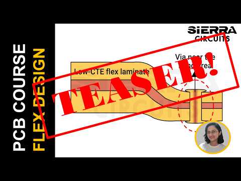
While routing, sharp trace corners might add mechanical stress; hence, use curved traces. Do not place vias in the bend areas, as this might compromise structural integrity.
Optimize the transition zones between rigid and flex sections. Maintain ≥50 mil hole-to-bend clearance; otherwise, it might lead to hole wall damage during bending.
In ensuring electrical performance and flexibility, ground plane design plays a crucial role. You may choose solid planes for better grounding. However, the downside is that they may crack under repeated bending. Therefore, prefer cross-hatched patterns.
What you’ll learn:
- Why you shouldn’t design a flex board like a rigid one
- Stack-up flaws that can compromise reliability
- How to choose flex PCB materials
- Bend radius rules you cannot ignore
- Techniques to ensure uniform impedance
- Ground plane strategies: Solid vs. cross-hatched
- Best practices for component placement
- IPC standards that govern flexible designs
- Common DFM mistakes and how to prevent them
About Vandana CC
Engineering Project Coordinator at Sierra Circuits
With a strong foundation in physics, Vandana CC brings a deep technical understanding to her work in PCB design and electronics manufacturing. She holds a Master’s in Physics and has experience teaching before transitioning into research at the Indian Institute of Science.
At Sierra Circuits, Vandana has played a key role in R&D projects, contributing to the development of engineering tools and calculators, technical content creation, and customer demos. Currently, she focuses on project coordination, ensuring seamless collaboration both within the team and with external partners. Her expertise bridges the gap between technical innovation and practical application, making her an integral part of Sierra Circuits’ engineering efforts.
Watch the Trailer